© 2009 MIMAKI ENGINEERING CO.,LTD.
2.3.1 P.1
1
2
3
4
5
6
7
8
R.1.1
Maintenance Manual > Electrical Parts > Circuit Board Specifications > Power Supply PCB Assy
Model CJV30/TPC Issued 2008.08.04 Revised 2008.09.17 F/W ver. 1.20 Remark
1.1
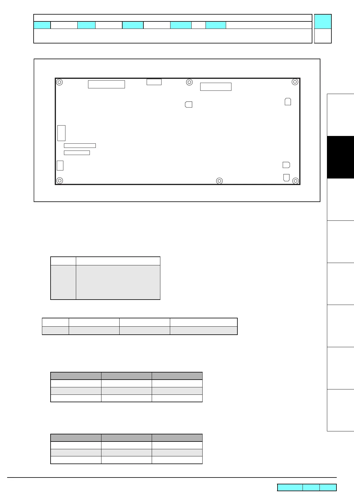
2.3.1 Power Supply PCB Assy
Outline
Board name: Power Supply PCB Assy
This PCB provides all the electrical power for controlling and driving functions.
Input and output of the power source
Fuse rating
Connector specification
CN1 AC input connector
Model number (JST): B2P3-VH (LF) (SN)
CN2 AC HEAT input connector
Model number (JST): B03P-VL *Media heater power input
Input AC100-120V, AC220-240, 50/60Hz
Output +3.3SBV, 5.5A
+5SBV, 1.0A
+5V, 4.2A
+24V, 5.0A
+42V, 4.0A
F1 T6.3AH/ 250V 5x20 mm Input line to DC output circuit
F3 T15AH/ 250V 6.3x30 mm Input line to heater
Pin Terminal name Type
1 AC-L AC input supply
2 (NC) (NC)
3 AC-N AC input supply
Pin Terminal name Type
1 AC-L AC input supply
2 (NC) (NC)
3 AC-N AC input supply
CN1
CN2
F3
CN3
CN4
CN5
VR2
VR4
VR3
VR1
F1
 Loading...


