© 2009 MIMAKI ENGINEERING CO.,LTD.
2.3.11 P.1
1
2
3
4
5
6
7
8
R.1.1
Maintenance Manual > Electrical Parts > Circuit Board Specifications > LED PCB Assy
Model CJV30/TPC Issued 2008.08.04 Revised 2008.09.17 F/W ver. 1.20 Remark
1.1
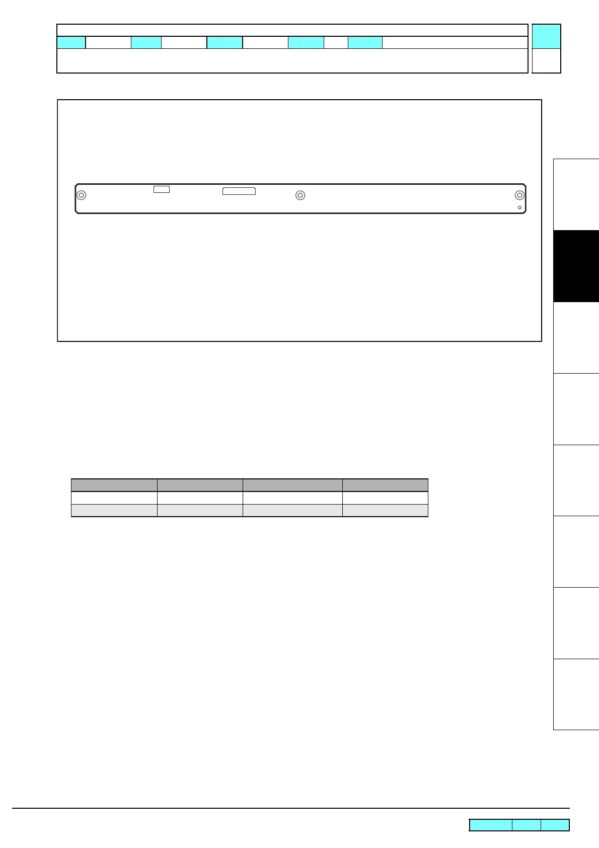
2.3.11 LED PCB Assy
Outline
Board name: LED PCB Assy
Is located at the front of the ink cartridge unit inside the left cover.
The FFC from the X-axis relay PCB assy is connected to this PCB. The LEDs (green, red) corresponding to each slot
of the cartridge is displayed on the LED PCB assy.
List of connectors
CN No Pin Connected to: Remarks
CN1 20 X-axis Relay PCB Assy
CN2 6 None AUX.
 Loading...


