Main Unit Theory of Operation
1 - 4 0070-10-0705 Passport V™ Service Manual
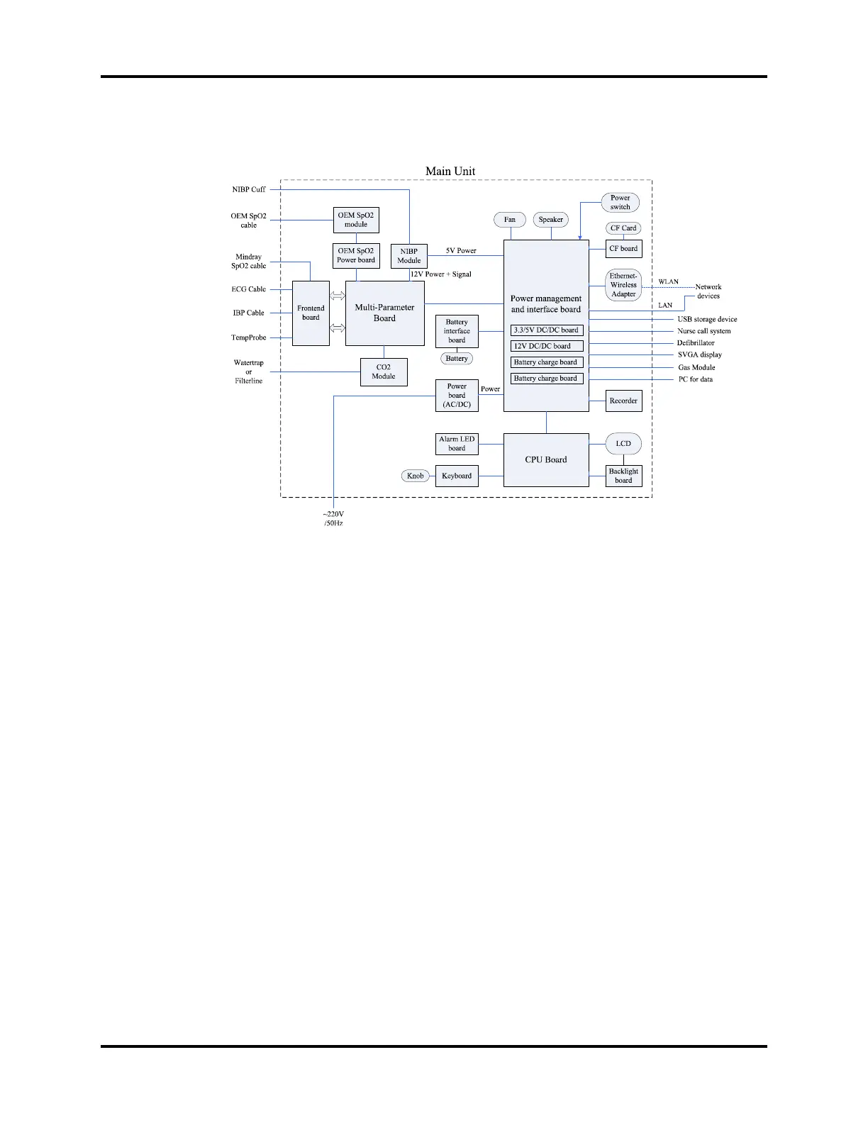
The following diagram illustrates the structure of the patient monitor.
FIGURE 1-3 Patient monitor structure
1.3.1 Input System
Keypad
The keypad, located at the lower part of the monitor’s front panel, contains 18 keys, AC
status LED and battery status LED, and also provides a connection for the knob to the CPU
board.
Knob
The knob can be pressed, or rotated either clockwise or counter-clockwise. It connects to the
keypad.
Power switch
The power switch, located at the right side of the monitor, is a single-throw rocker switch.
Pressing it will power the monitor on or off. The power switch’s status is detected by the
power management and interface board.
1.3.2 Output System
LCD Panel
The monitor uses an LCD panel with a resolution of 800x600, which runs power and gets
digital signals from the CPU board. The backlight is powered by the backlight board, which
is powered by the CPU board.
 Loading...