EasyManua.ls Logo

Mindray VS-900 Service Manual

Mindray VS-900
122 pages
To Next Page IconTo Next Page
To Previous Page IconTo Previous Page
Page #115 background imageLoading...
Page #115 background image
A-5
A.6 Patient Leakage Current
Patient leakage currents are measured between a selected applied part and mains earth. All
measurements have a true RMS only response.
Preparation
Perform a calibration from the Mains on Applied Part menu.
The following outlet conditions apply when performing this test:
Normal Polarity, Earth Open, Outlet ON Normal Polarity, Outlet ON
Normal Polarity, L2 Open, Outlet ON Reversed Polarity, Outlet ON
Reversed Polarity, Earth Open, Outlet ON Reversed Polarity, L2 Open, Outlet ON
WARNING
If all of the applied parts correspond to the instrument type, the applied parts will
be tied together and one reading will be taken. If any of the applied parts differ
from the instrument type, all applied parts will be tested individually, based on the
type of applied part. This applies to Auto and Step modes only.
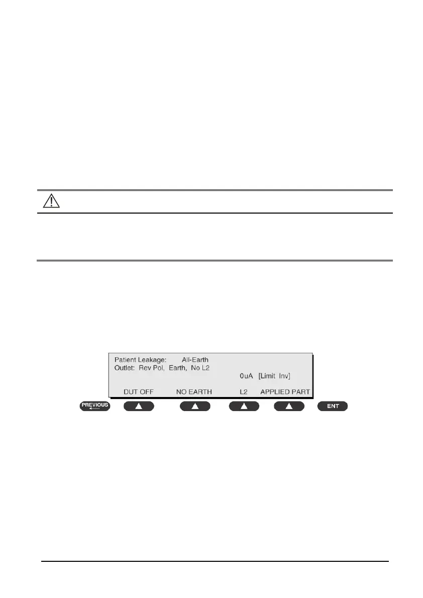
To Perform the Test
1. From the MAIN MENU, or with the outlet unpowered, plug the DUT into the 601PRO
front panel outlet, and turn on the device.
2. Attach the applied parts to the 601PRO's applied part terminals.
3. Press shortcut key 6. The Patient Leakage test is displayed, and the test begins
immediately.
4. Press APPLIED PART (SOFT KEY 4) at any time to select the desired applied part leakage
current.
5. Modify the configuration of the front panel outlet by pressing the appropriate SOFT
KEY on the 601PRO.
6. Press the print data key at any time to generate a printout of the latest measurement.
In Case of Failure
Check any broken of the enclosure. Replace any defective part.
Inspect wiring for bad crimps, poor connections, or damage.

Table of Contents

Other manuals for Mindray VS-900

Questions and Answers:

Mindray VS-900 Specifications

General IconGeneral
RESPImpedance Respiration
Display Size12.1 inch
ParametersECG, SpO2, NIBP, RESP, TEMP
ECG3-lead or 5-lead ECG monitoring
IBPOptional, up to 2 channels
CO2Optional, Sidestream or Mainstream CO2 monitoring
AGO2, N2O, CO2
ANESMultiple anesthetic agents
ConnectivityEthernet, USB
Power SupplyAC power and battery

Summary

Preface

Manual Overview and Access

Covers manual purpose, audience, and access passwords.

Introduction

Manual Information and Safety

Covers manual details, safety warnings, and equipment symbols.

Theory of Operation

System Overview and Components

Describes monitor purpose, architecture, connectors, and main unit parts.

Equipment Installation

Preparation and Procedure

Guides on unpacking, site/environmental/electrical prep, and installation steps.

Testing and Maintenance

General Inspection and Module Tests

Covers intro, visual inspection, power-on, and module performance tests.

Troubleshooting

Problem Identification and Resolution

Covers common issues, causes, and step-by-step troubleshooting guides.

Disassembly and Repair

Tools, Preparations, and Main Unit Steps

Lists tools, preparations, and disassembly procedures for the main unit.

Parts Identification

Main Unit and Front Housing Parts

Lists parts of the main unit and touchscreen/non-touchscreen front housings.

Component Parts Lists

Rear Housing, Bracket, and Module Assemblies

Lists parts for rear housing, bracket, power management, connector panels, and various modules.

Hardware and Software Upgrade

Hardware Upgrade Procedures

Details how to upgrade hardware components like modules, touchscreen, and recorder.

Software Upgrade Process

Explains how to upgrade system and module software using the upgrade tool.

Electrical Safety Inspection

Inspection Procedures and Criteria

Covers power cord, enclosure, labeling, earth resistance, and leakage tests.

Related product manuals