2-5
Keypad
The keypad scans and detects the input of keys and knobs, integrates the power on/off key,
and connects AC and battery indicators.
Alarm Lamp Board
The alarm lamp board is located at the top of front housing. It has two-color indicators, red
and yellow. The alarm lamp board directly connects the main board through a cable. It is
controlled directly by the main board.
Touchscreen and Touchscreen Control Board
The touchscreen control board drives the touchscreen and implements communication with
the vital signs monitor.
Wi-Fi Module
The Wi-Fi enable the equipment to connect to 802.11 g/n wireless network.
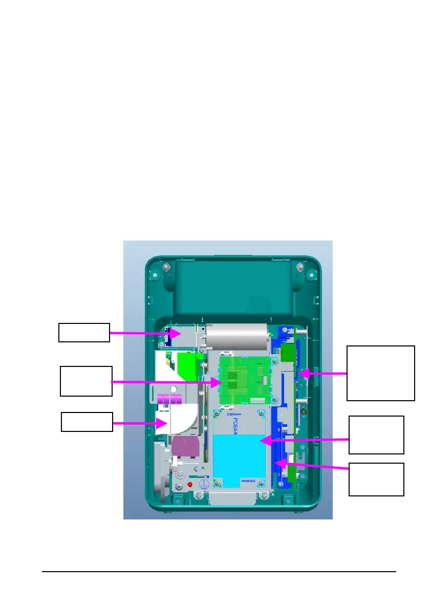
2.6 Rear Housing Assembly
Rear housing assembly consists of power module (AC/DC), power management and
interface board (including SpO
2
isolation power), recorder, speaker, battery, NIBP module,
and SpO
2
board (including three types of configuration, i.e. Mindray, Masimo, and Nellcor).
Power
management
and interface
board
SpO
2
board
NIBP
module
Speaker
AC/DC
power
module
Recorder
 Loading...