FA-200 Series Installation and Operation Manual
9
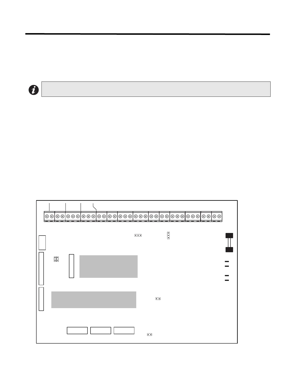
Module Settings
Main Fire Alarm Module
Class A / B Selection
On the FA-202, FA-204 and FA-204E only, JW1 & JW2 are connected from 1 to 2 for initiating circuit Class B (Style
B) operation, and from 2 to 3 for Class A (Style D) operation. These are not present on the FA-201, and only JW2 is
present on the FA-202.
Zone Adder Module: On an FA-204E only, remove the jumper on JW4 if a DM-204 Zone Adder Module is installed.
The zone adder module is plugged into P6 & P7.
Relay Module: Remove the jumper on JW3 if an RM-204 or RM-208 Relay Module is installed. The relay module is
plugged into P1.
Digital Communicator: Remove the jumper on JW6 if a DACT-100A Digital Communicator is installed. The digital
communicator is plugged into P8.
City Tie: Remove the jumper on JW6 if a PR-100 City Tie is installed. The City Tie is plugged into P8.
Battery: Connected to P2(+) & P3(-) via the factory installed cables.
Transformer: Factory wired to P4 & P5, do not disconnect.
JW5: There should be no jumper here; do not use.
SW9,11,13: Configuration DIP switches.
Battery Fuse F1: Replace with 10 amp, 1-1/4" fast acting fuse.
Figure 5: Main Fire Alarm Module
Note: The Class A/B selection affects all initiating circuits, and must be used with the correct Configuration
DIP switch setting.
P6
F1
10 AMP
BATTERY
FUSE
SW13
1
2
3
JW2
P3
231
BATT+
P4
P5
P2
BATT-
XMFR
XMFR
JW1
P7
P8
JW4
JW5
JW3
JW6
SW11
SW9
P1
SUPV RLY
COM-
COM+
S
IND2-
IND2-
IND1-
IND1-
IND1+
IND1+
INI4-
INI4+
INI3-
INI3+
INI2-
INI2+
INI1-
INI1+
485-
485+
-
+
TRB
TRL
IND2+
IND2+
NO
NC
COM
ALM RLY
NO
NC
COM
TBL RLY
4 WIRE
NO
NC
COM
Note: Do not plug DACT into P1 on main
board. Plug into P8 only when system is
powered off.
Note: Do not plug RM-204/
208 into P8 on main board.
Plug into P1 only when
system is powered off.

 Loading...


