Indicators, Controls, & Operation
22
Indicators, Controls, & Operation
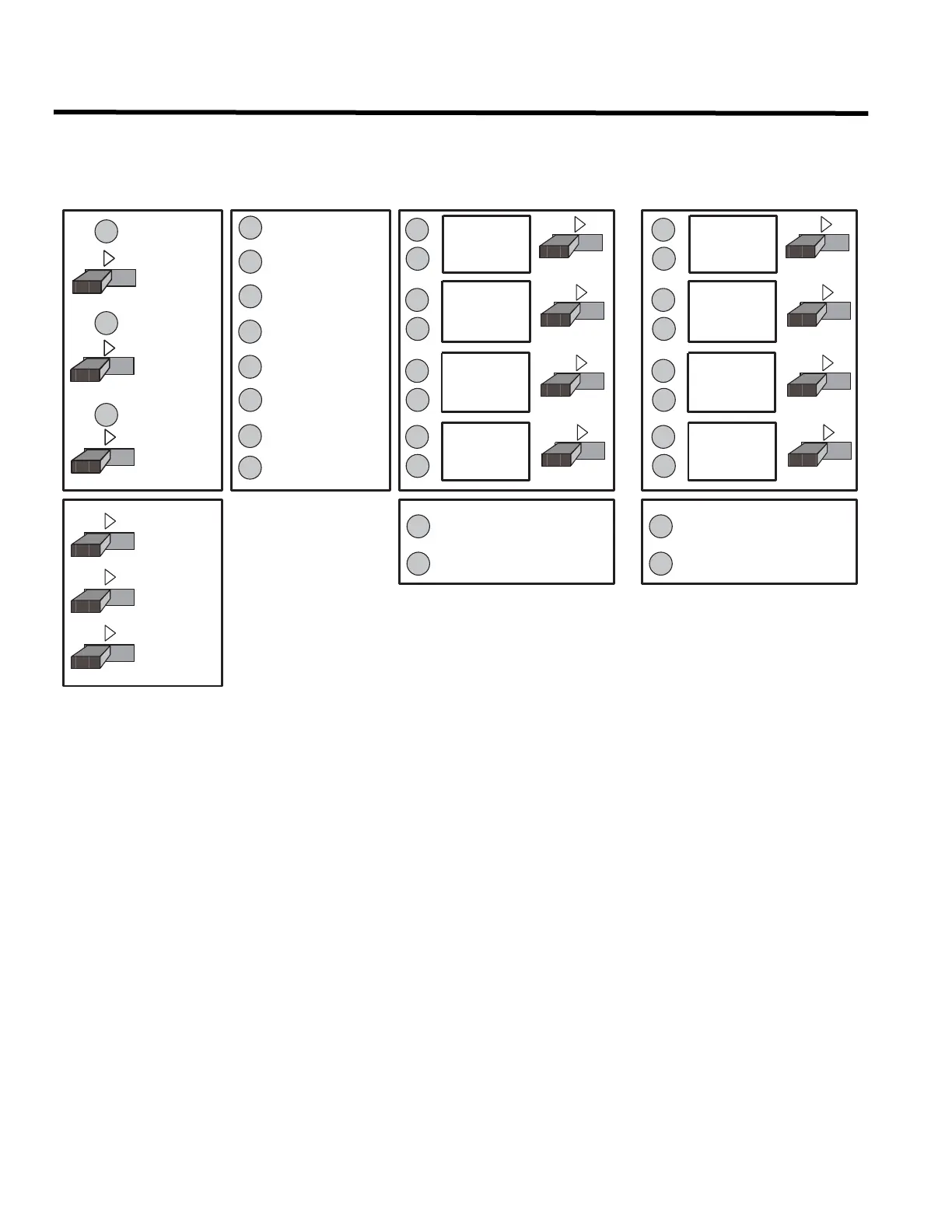
Refer to Figure 17 below for LED Indicators and control switch locations.
Figure 17: Indicators and Control Location
Indicators
Buzzer
The buzzer is activated by any of the following:
• Fire alarm: steady
• Supervisory alarm: steady
• Trouble: trouble flash rate
If the buzzer turns on in response to a non-latching trouble or supervisory, it will be turned off if the condition causing
it goes away and there is no other reason for it to be on.
AC On LED
The green AC On LED illuminates steadily while the main AC power is within acceptable levels. It turns off when the
level falls below the power-fail threshold and the panel switches to standby (battery) power.
Common Alarm LED
The Common Alarm indicator turns on steady red whenever the panel is in alarm as a result of an alarm on any
initiating circuit. Since all alarms are latched until the panel is reset, the indicator will remain on until reset.
FIRE
DRILL
SIGNAL
SILENCE
AUXILIARY
DISC.
A.C. ON
COMMON
ALARM
COMMON
SUPERVISORY
COMMON
TROUBLE
BATTERY
TROUBLE
GROUND
FAULT
REMOTE
TROUBLE
TEST
DISC. 1
ZONE 1
ZONE 2
ZONE 3
ZONE 4
DISC. 2
DISC. 3
DISC. 4
DISC. 1
ZONE 5
ZONE 6
ZONE 7
ZONE 8
DISC. 2
DISC. 3
DISC. 4
SIG.ZONE 2
TROUBLE
SIG.ZONE 1
TROUBLE
SIG.ZONE 4
TROUBLE
SIG.ZONE 3
TROUBLE
SYSTEM
RESET
BUZZER
SILENCE
LAMP
TEST

 Loading...


