FA-200 Series Installation and Operation Manual
19
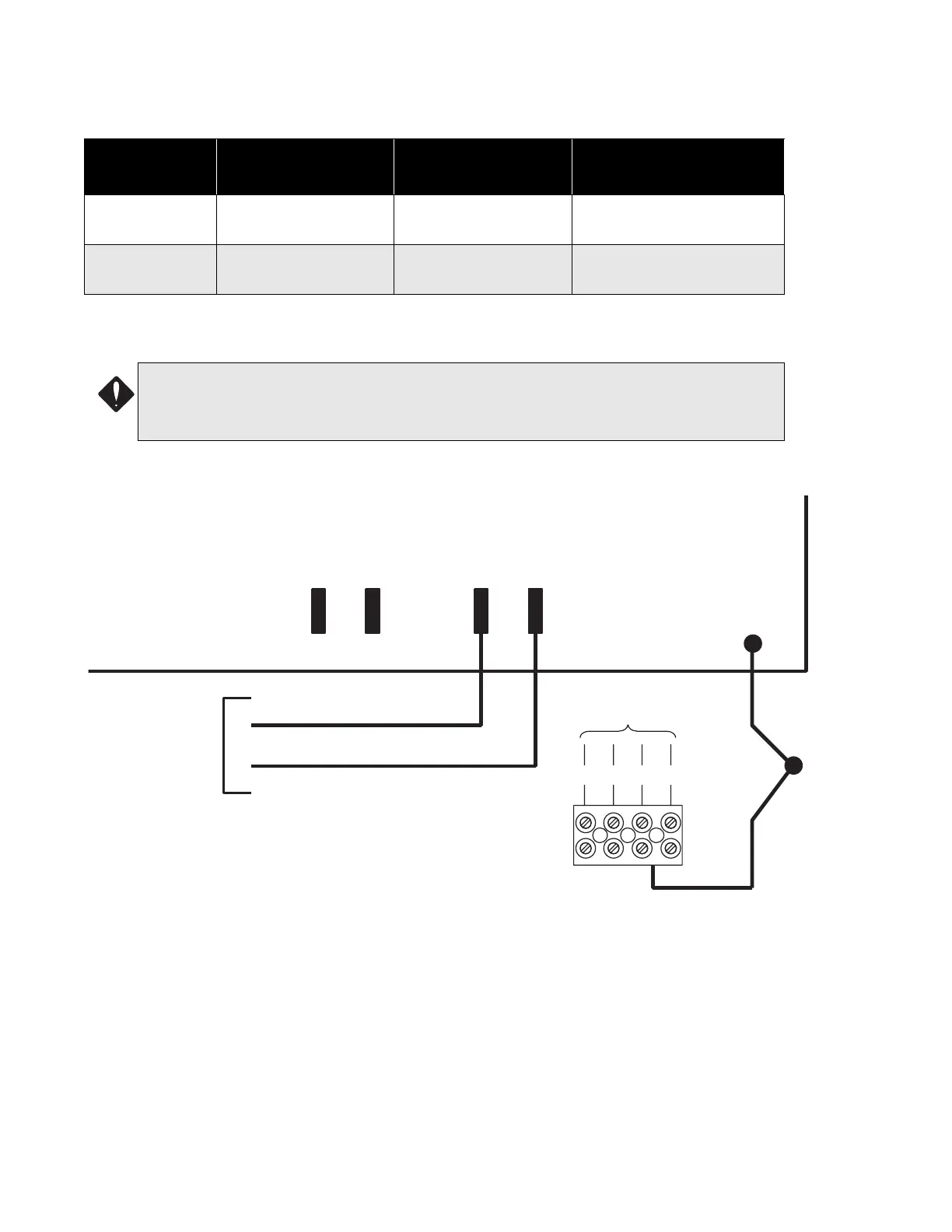
Power Supply Connections
The power supply is part of the main fire alarm module and the chassis. The ratings are:
See Appendix C on page 38 for module specifications. Wire as shown in Figure 16 below, using proper wire
gauges.
Figure 16: Power Supply Connections
Model
Electrical Input
Ratings
Power Supply Total
Current
Battery Fuse on Main
Module
FA-201, FA-202,
FA-204
120 V 60Hz 2A /
240V 50 Hz 1A
2.75 A maximum
F1: Replace with 10 amp, 1-
1/4" fast acting fuse
FA-204E
120 V 60Hz 2A /
240V 50 Hz 1A
6 A maximum
F1: Replace with 10 Amp,
1-1/4" Fast Acting Fuse
ATTENTION:
• Do not exceed power supply ratings:
• To prevent sparking, connect batteries after the systems main A.C. power is turned on.
P2
MAIN FIRE ALARM MODULE
GREEN
TO 24 VDC
BATTERY
BLACK
P4P5 P3
+
-
BAT
RED
EARTH GROUND
DIMPLE ON
ENCLOSURE,
FOR
GROUNDING
WIRES AND
SCREW.
GREEN EARTH GROUND
WIRE SOLDERED ONTO MAIN
FIRE ALARM MODULE PCB.
LL
N
G
TO DEDICATED
BRANCH CIRCUIT
240V, 50Hz
120V, 60Hz

 Loading...


