FA-200 Series Installation and Operation Manual
11
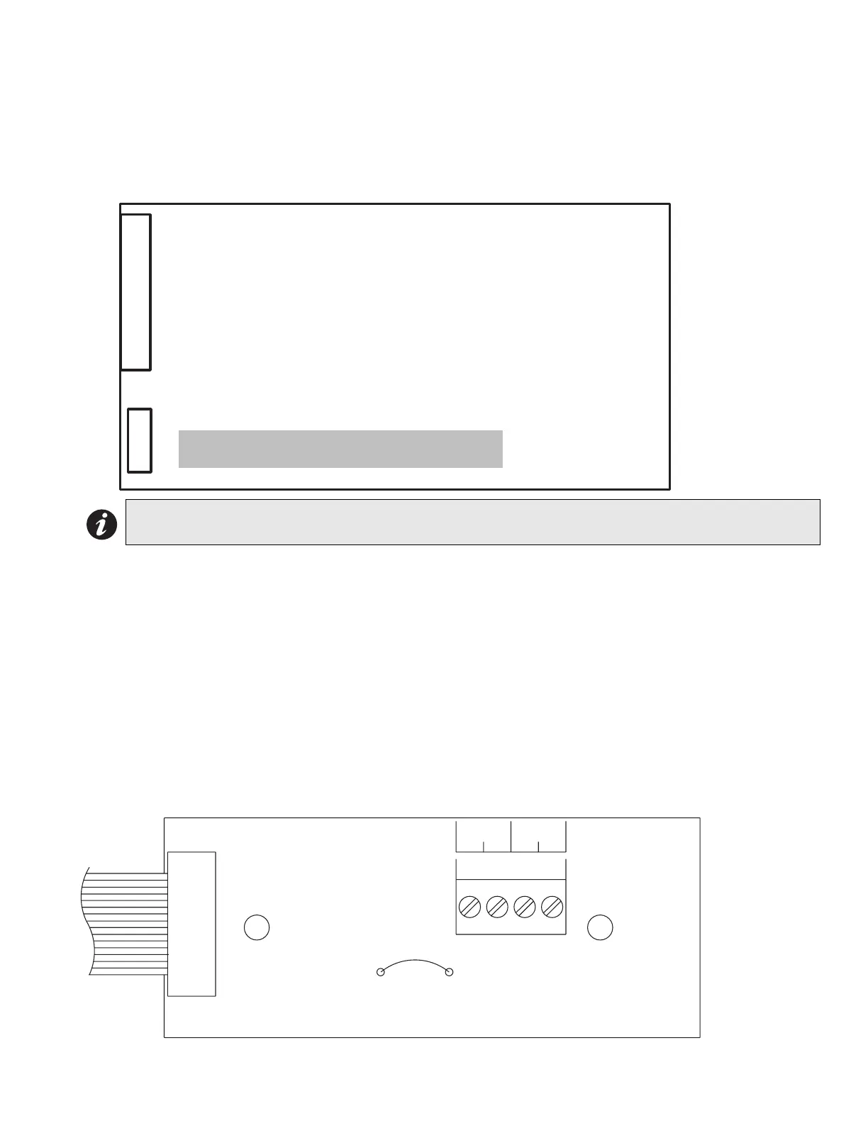
DACT / Dialler Module (Model DACT-100A)
P1: Cable to P8 on the main fire alarm board.
Jumper JW6 on the main fire alarm module must be removed if a DACT-100A is installed. note that this module
cannot be installed if a polarity reversal and city tie module is used.
Figure 8: DACT-100A Dialer Module
Please see the DACT-100A Manual (LT-639) for more information.
Polarity Reversal and City Tie Module (Model: PR-100)
P1: Cable to P8 on the main fire alarm module.
JW1: Cut this jumper for trouble transmission. When this jumper is cut and a system trouble occur, the designated
terminals will transmit a "zero volts" or "open" circuit. Please note that at normal condition, the terminals polarity is
read exactly as labelled on the circuit board.
Jumper JW6 on the main fire alarm module must be removed if a polarity reversal and city tie module is installed.
note that this module cannot be installed if a DACT / dialler module is used.
Figure 9: PR-100 Polarity Reversal and City Tie Module
Note: The DACT is Tip & Ring sensitive. If any of the two LEDs are illuminated amber, reverse the wiring,
then wait 30 seconds for the LED to clear.
P1
FIELD WIRING TERMINALS
Note: Do not plug DACT into P1 on main board.
Plug it into P8 only when the system is powered off.
JW1
P1
CITY
TIE
+ -
POL.
RVS.
+ -

 Loading...


