FA-200 Series Installation and Operation Manual
41
Appendix D: Power Supply & Battery Calculations
Use the form below to determine the required main chassis and secondary power supply (batteries).
Total Current Requirement
ALARM (B)______ Amps.
Battery Capacity Requirement
([STANDBY (A) ______ ] X [(24 or 60 Hours) ___ ]) + ([ALARM (B) ______ ] X [
♣
Alarm in Hr.] _____) = (C) ______AH
* Assuming three initiating circuits in alarm.
♣
Use 0.084 for five minutes of alarm or 0.5 for thirty minutes of alarm as a multiplier figure.
♦
Using the MIR-425/U 2-wire smoke detector. See Appendix A on page 33 for other available smoke detectors.
Total Alarm Current
• Must be 2.75 amperes or less for FA-201, FA-202, and FA-204. Indicating Circuits not to exceed 2.4 amperes.
• Must be 6 amperes or less for FA-204E. Indicating Circuits not to exceed 5 amperes.
Battery Selection
• Multiply (C) by 1.20 to derate battery.
• Use BA-1065(6.5AH) Batteries for the FA-201, FA-202, and FA-204 which charges up to 12 AH Batteries.
• Use BA-110(10AH) Batteries for the FA-204E.
• The FA-204E will charge up to 24AH batteries if they are in an external Mircom BC-160 Battery Cabinet.
IMPORTANT NOTICE
The main AC branch circuit connection for Fire Alarm Control Unit must provide a dedicated
continuous power without provision of any disconnect devices. Use #12 AWG wire with 600-volt
insulation and proper over-current circuit protection that complies with the local codes. Refer to
Appendix C on page 38 for specifications.
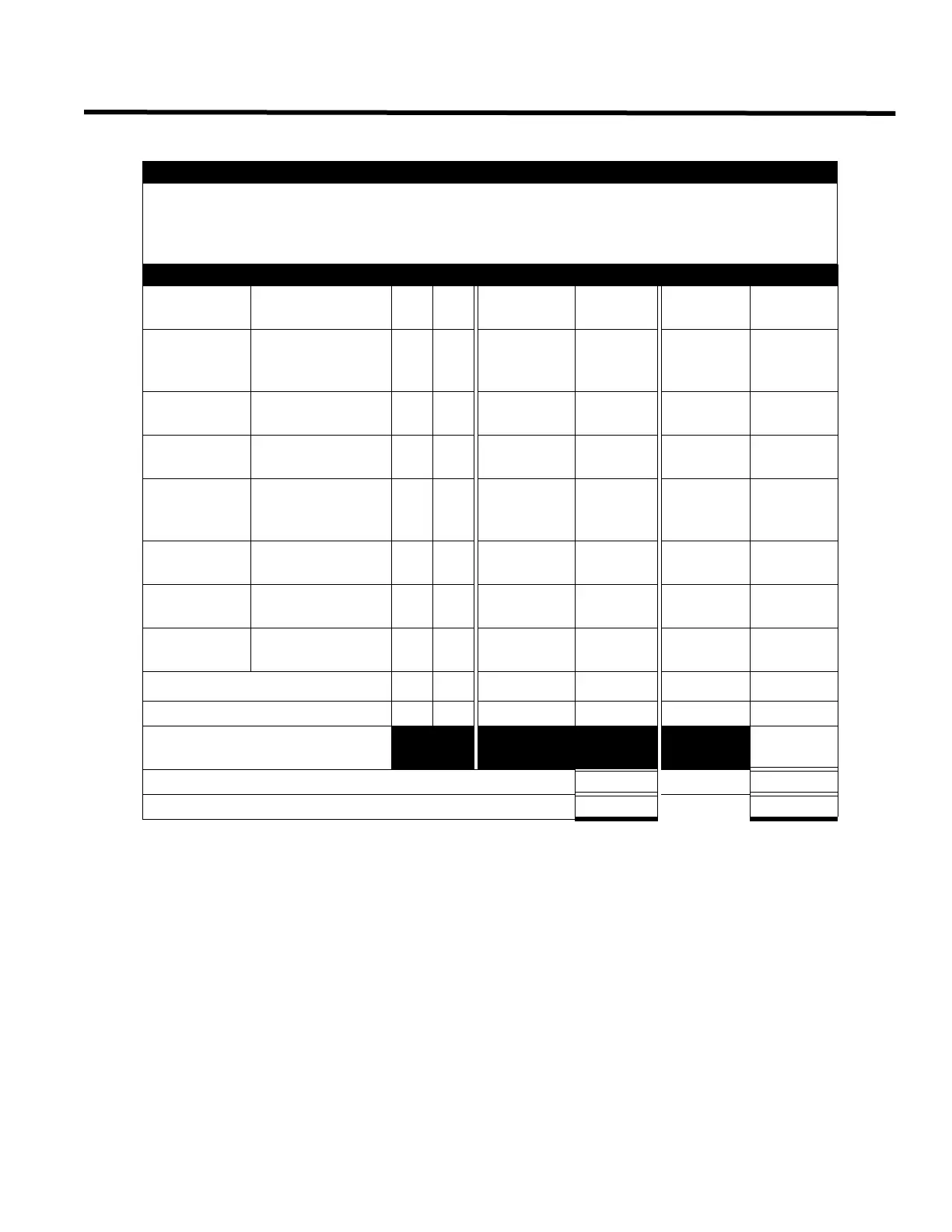
Power Requirements (All currents are in amperes)
Model
Number
Description
Qt
y
Standby
Total
Standby
Alarm
Total
Alarm
FA-201, FA-
202, FA-204,
FA-204E
Fire Alarm
Control Panel
X 0.110 = 0.220 =
DM-204
Zone Adder
Module
X 0.045 = 0.120 =
RM-204/RM-
208
Relay Module X 0.005 = 0.160 =
PR-100
Polarity Reversal
and City Tie
Module
0.035 = 0.300 =
DACT-100A
DACT/Dialler
Module
0.045 = 0.120 =
RAM-208
Remote
Annunciator
0.035 = 0.090 =
RTI-1
Remote Trouble
Indicator
0.035 = 0.035 =
Two-Wire Smoke Detectors
♦
0.0001
= * 0.090 = 0.090
Four-Wire Smoke Detectors X = =
Signal Load (bells, horns,
strobes, and etc.)
=
Auxiliary Power Supply for Remote Annunciators Alarm =
Total currents (Add above currents) STANDBY (A)(B)

 Loading...


