Field Wiring
16
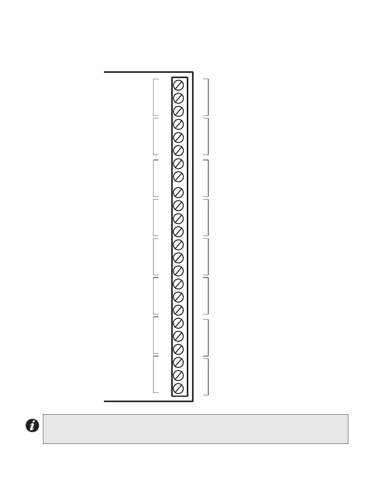
Relay Module (RM-204 or RM-208) Terminal Connections
Note that only relays #1 to #4 are present on the RM-204.
Figure 13: Relay Module (RM-204 or RM-208) Terminal Connections
Notes:
• All power limited circuits must use type FPL, FPLR, or FPLP power limited cable. Must be connected to a
listed power limited source of supply.
NO
NC
RELAY #2
COM
NO
NC
RELAY #1
COM
NO
NC
RELAY #3
COM
NO
NC
RELAY #4
COM
NO
NC
RELAY #5
COM
NO
NC
RELAY #6
COM
NO
NC
RELAY #7
COM
NO
NC
RELAY #8
COM
RELAY CONTACTS
28 VDC, 1 AMP
RESISTIVE LOAD
RELAY CONTACTS
28 VDC, 1 AMP
RESISTIVE LOAD
RELAY CONTACTS
28 VDC, 1 AMP
RESISTIVE LOAD
RELAY CONTACTS
28 VDC, 1 AMP
RESISTIVE LOAD
RELAY CONTACTS
28 VDC, 1 AMP
RESISTIVE LOAD
RELAY CONTACTS
28 VDC, 1 AMP
RESISTIVE LOAD
RELAY CONTACTS
28 VDC, 1 AMP
RESISTIVE LOAD
RELAY CONTACTS
28 VDC, 1 AMP
RESISTIVE LOAD

 Loading...


