Field Wiring
20
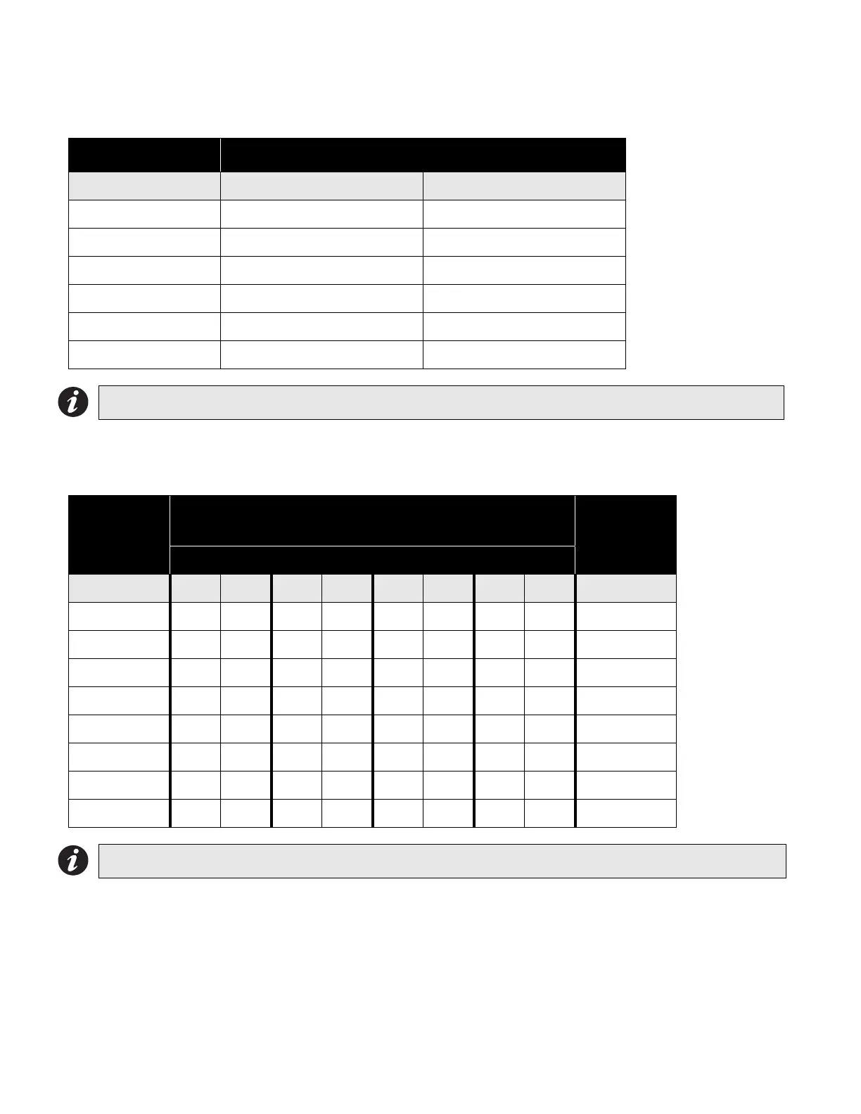
Wiring Tables
Table 1: Wiring Table for Initiating Circuits.
Table 2: Wiring Table for Indicating Circuits
Main board indicating circuits are rated for 1.7 amps each. The SGM-1004(A) indicating circuits are rated for 1.7
amps each.
RS-485 Wiring: See the wiring information for the remote annunciator being used.
4-Wire Smoke Wiring: The maximum allowable current is 0.2 amperes. The maximum allowed voltage drop is 1
volt. Refer to Table 2: WIring for Indicating Circuits above.
Wire Gauge Maximum Wiring Run to Last Device (ELR)
(AWG) ft. m
22 2990 910
20 4760 1450
18 7560 2300
16 12000 3600
14 19000 5800
12 30400 9200
Note: Maximum loop resistance should not exceed 100 Ohms.
Total Signal
Load
Maximum Wiring Run to Last Device (ELR)
Max Loop
Resistance
18AWG 16AWG 14AWG 12AWG 0hms
Amperes ft. m ft. m ft. m ft. m Ohms
0.06 2350 716 3750 1143 6000 1829 8500 2591 30
0.12 1180 360 1850 567 3000 915 4250 1296 15
0.30 470 143 150 229 1200 366 1900 579 6
0.60 235 71 375 114 600 183 850 259 3
0.90 156 47 250 76 400 122 570 174 2
1.20 118 36 185 56 300 91 425 129 1.5
1.50 94 29 150 46 240 73 343 105 1.2
1.7 78 24 125 38 200 61 285 87 1.0
Note: Maximum voltage drop should not exceed 1.8 volts.

 Loading...


