MDS-E/EH Series Instruction Manual
2 Wiring and Connection
87
IB-1501229-F
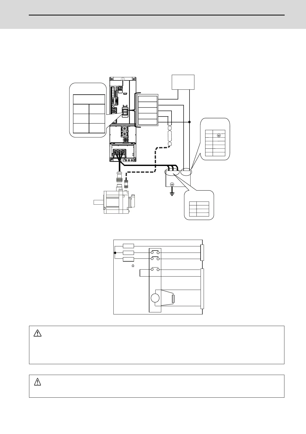
2.6.2 Dynamic Brake Unit Wiring
The servo drive units of MDS-E-V1-320W or larger and MDS-EH-V1-160W or larger do not have built-in dynamic brakes.
Always install a dynamic brake unit.
The servo drive units of MDS-E-V1-320 or smaller or MDS-EH-V1-160 or smaller have built-in dynamic brakes.
CAUTION
Correct wire the dynamic brake unit to the servo drive unit.
Do not use for applications other than emergencies (normal braking, etc.). The internal resistor could heat up, and lead to
fires or faults.
POINT
When you use a servo motor with a brake, please wire (between 3A pin and 3B pin) of CN20 connector.
1A :
P24
2A :
DBR
3A :
MBR1
3B :
MBR2
1B :
24G
V
W
U
14
13
b
a
SK
R(0.5
)
V
W
2
1
3
U
UVW a b
NC
a
b
13
14
5
6
2
1
3
4
M
(MDS-D-DBU)
(CN20)
3B
(MBR2)
3A
(MBR1)
2B
(N.C.)
2A
(DBR)
1B
(24G)
1A
(P24)
GND24VDC
Brake connector
External
power supply
Control terminal
block (M3)
Dynamic brake unit
Power terminal
block (M3)
Internal circuit diagram
Servomotor
Terminal
Name
Terminal
Name
Terminal block
Twist wire
Pin
(Name)
 Loading...