MDS-E/EH Series Instruction Manual
2 Wiring and Connection
49
IB-1501229-F
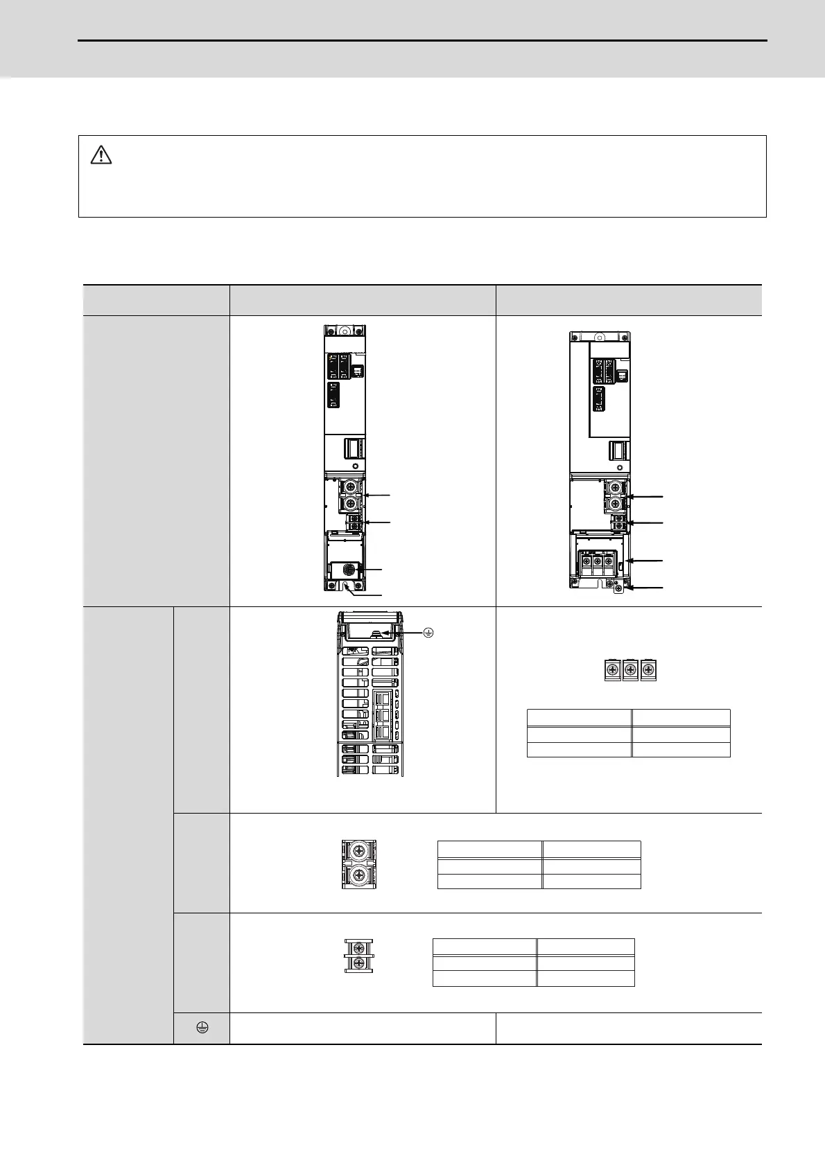
2.2.2 Connector Pin Assignment
(1) Main circuit terminal block and connector
Power supply unit
(Note) The illustrations of drive units are shown as an example.
CAUTION
Do not apply a voltage other than that specified in Instruction Manual on each terminal. Failure to observe this item could
lead to rupture or damage, etc.
Unit
Terminal
MDS-E-CV-37 to 75
MDS-E-CV-110 to 185
MDS-EH-CV-37 to 185
Terminal
position
Terminal
specification/
Pin
assignment
[1] TE1
[2] TE2
[3] TE3
[4]
Screw size: M4×12
Tightening torque: 1.2Nm
The PE screw size is the same as TE1.
2
3
4
1
4
1
L3
L2
L1
(Note) This is a bottom view.
2.0Nm
M5 x 12
L1 L2 L3
Compatible unit
Screw size
Tightening torque
All of CV
4.0Nm
M6 x 18
L+
L-
Compatible unit
Screw size
Tightening torque
All of CV
M4 × 10
1.2Nm
L11
L21
Compatible unit
Screw size
Tightening torque
All of CV
 Loading...