EasyManuals Logo

Motorola 700 Series User Manual

Motorola 700 Series
156 pages
To Next Page IconTo Next Page
To Previous Page IconTo Previous Page
Page #52 background imageLoading...
Page #52 background image
2-4
Hardware Preparation and Installation
2
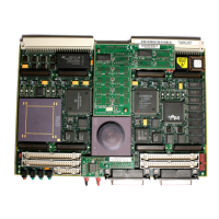
Figure 2-1. MVME162LX Board Layout
S1 S2
P1
A1
B1
C1
A32
B32
C32
11856.00 9708
MVME
162-7XX
PRIMARY SIDE
P2
A32
B32
C32
A1
B1
C1
49
50
1
2
J3
49
50
1
2
J4
19
20
J2
DS2
DS1
1
2
1
J1
49
50
24
25
27
26
2
1
J6
49
J8
J5 J7
4
2
3
J19
SCSI INTERFACE
CSL
FUSES
FAIL
RUN
SCON
ABORT
RESET
99
100
1
2
J15
49
50
24
25
27
26
2
1
49
50
24
25
27
26
2
1
49
50
24
25
27
26
2
1
3
J9
81
15 9
J23
34 2
33 1
68
67
36
35
ABCD
28
17
28
17
28
17
28
17
J17
99
100
1
2
J22
J21
16 15
21
J20
16
21
1
J18
12
15
J16
12
J11
31
2
6
J14
1
5
J12
21
1324
ETHERNET PORT
BT1

Table of Contents

Questions and Answers:

Question and Answer IconNeed help?

Do you have a question about the Motorola 700 Series and is the answer not in the manual?

Motorola 700 Series Specifications

General IconGeneral
BrandMotorola
Model700 Series
CategoryController
LanguageEnglish

Related product manuals