Home
Motorola
Controller
700 Series
Motorola 700 Series User Manual
5
of 1
of 1 rating
156 pages
Give review
Manual
Specs
To Next Page
To Next Page
To Previous Page
To Previous Page
Loading...
Installation Instructions
2-21
2
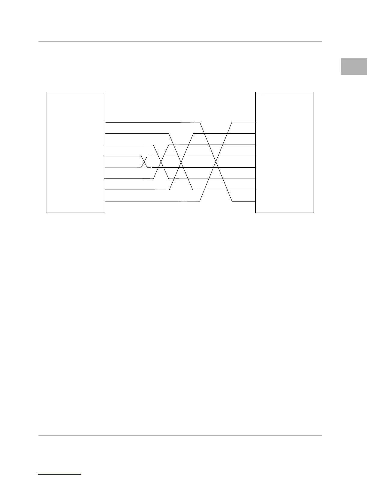
Figure 2-4 diagrams the pin assignments required in a typical 8-
conductor serial cable having RJ-45 connectors at both ends. Note
that all wires are crossed.
Figure 2-4. T
ypical RJ-45 Serial Cable
RXD
TXD
CTS
RTS
DCD
DTR
1
2
3
4
5
6
7
8
RJ-45 CONNECTOR
RJ-45 CONNECTOR
8
7
5
4
6
2
1
SG
3
SG
68
70
Table of Contents
Default Chapter
9
Table of Contents
9
Chapter 1 Board Level Hardware Description
15
Introduction
15
Overview
15
Related Documentation
17
Documents for the MVME162LX
18
Other Applicable Motorola Publications
18
Applicable Non-Motorola Publications
19
Requirements
20
Features
20
Table 1-1. 700/800-Series MVME162LX: Features
20
Specifications
22
Table 1-2. 700/800-Series MVME162LX: Specifications
22
Cooling Requirements
23
Special Considerations for Elevated-Temperature Operation
23
FCC Compliance
25
Manual Terminology
25
Block Diagram
27
Functional Description
27
Front Panel Switches and Indicators
27
Figure 1-1. MVME162LX Block Diagram
28
Data Bus Structure
29
Microprocessor
29
MC68040 Cache
29
No-Vmebus-Interface Option
30
Memory Options
30
DRAM Options
30
SRAM Options
31
About the Battery
32
EPROM and Flash Memory
34
Battery Backed up RAM and Clock
34
Vmebus Interface and Vmechip2
34
I/O Interfaces
35
Serial Communications Interface
35
Industrypack (IP) Interfaces
36
Optional Ethernet Interface
36
Optional SCSI Interface
37
SCSI Termination
37
Local Resources
38
Programmable Tick Timers
38
Watchdog Timer
38
Software-Programmable Hardware Interrupts
39
Local Bus Timeout
39
Local Bus Arbiter
40
Connectors
40
Table 1-3. Local Bus Arbitration Priority
40
Memory Maps
41
Local Bus Memory Map
41
Normal Address Range
41
Table 1-4. Local Bus Memory Map
42
Table 1-5. Local I/O Devices Memory Map
44
Vmebus Memory Map
47
Vmebus Accesses to the Local Bus
47
Vmebus Short I/O Memory Map
47
Chapter 2 Hardware Preparation and Installation
49
Introduction
49
Unpacking Instructions
49
Hardware Preparation
49
Table 2-1. Jumper Settings
50
System Controller Select Header (J1)
51
Figure 2-1. MVME162LX Board Layout
52
IP Bus Clock Header (J11)
53
SCSI Terminator Enable Header (J12)
54
SRAM Backup Power Source Select Header (J14)
54
Flash Write Protect Header (J16)
55
IP Bus Strobe Select Header (J18)
56
IP DMA Snoop Control Header (J19)
56
Eprom/Flash Configuration Header (J20)
57
Table 2-2. J19 Snoop Control Encoding
57
Onboard Flash Disabled
58
Table 2-3. Eprom/Flash Mapping - 256K X 8 Eproms
59
Table 2-4. Eprom/Flash Mapping - 512K X 8 Eproms
59
Table 2-5. Eprom/Flash Mapping - 1M X 8 Eproms
59
General-Purpose Readable Jumpers Header (J21)
60
Table 2-6. Eprom/Flash Mapping - 1M X 8 Eproms
60
Memory Mezzanine Options
61
Installation Instructions
62
Table 2-7. Memory Mezzanine Stacking Options
62
IP Installation on the MVME162LX
63
MVME162LX Installation
64
System Considerations
66
Figure 2-2. DB-25 DTE-To-RJ-45 Adapter
68
Figure 2-3. DB-25 DCE-To-RJ-45 Adapter
68
Figure 2-4. Typical RJ-45 Serial Cable
69
Chapter 3 Debugger General Information
71
Overview of M68000 Firmware
71
Description of 162Bug
71
162Bug Implementation
73
Installation and Startup
73
Prom Versions
77
Autoboot
77
Romboot
79
Network Boot
80
Restarting the System
80
Reset
81
Abort
81
Break
82
SYSFAIL* Assertion/Negation
82
MPU Clock Speed Calculation
83
Memory Requirements
83
Disk I/O Support
85
Blocks Versus Sectors
85
Device Probe Function
86
Disk I/O Via 162Bug Commands
86
IOI (Input/Output Inquiry)
86
IOP (Physical I/O to Disk)
86
IOT (I/O Teach)
87
IOC (I/O Control)
87
BO (Bootstrap Operating System)
87
BH (Bootstrap and Halt)
87
Disk I/O Via 162Bug System Calls
87
Default 162Bug Controller and Device Parameters
89
Disk I/O Error Codes
89
Network I/O Support
89
Intel 82596 LAN Coprocessor Ethernet Driver
90
UDP/IP Protocol Modules
90
RARP/ARP Protocol Modules
91
BOOTP Protocol Module
91
TFTP Protocol Module
91
Network Boot Control Module
91
Network I/O Error Codes
92
Multiprocessor Support
92
Multiprocessor Control Register (MPCR) Method
92
GCSR Method
94
Diagnostic Facilities
95
Manufacturing Test Process
95
Chapter 4 Using the 162Bug Debugger
97
In this Chapter
97
Entering Debugger Command Lines
97
Terminal Input/Output Control
97
Debugger Command Syntax
99
Syntactic Variables
99
Expression as a Parameter
99
Address as a Parameter
101
Address Formats
102
Table 4-1. Debugger Address Parameter Formats
102
Offset Registers
103
Port Numbers
105
Entering and Debugging Programs
105
Creating a Program with the Assembler/Disassembler
106
Downloading an S-Record Object File
106
Read the Program from Disk
106
Calling System Utilities from User Programs
107
Preserving the Debugger Operating Environment
107
162Bug Vector Table and Workspace
108
Examples
108
Hardware Functions
109
Exception Vectors Used by 162Bug
109
Table 4-2. Exception Vectors Used by 162Bug
109
Exception Vector Tables
111
Using 162Bug Target Vector Table
111
Creating a New Vector Table
112
Floating Point Support
114
Single Precision Real
115
Double Precision Real
115
ScientifiC Notation
116
The 162Bug Debugger Command Set
116
Appendix A Configure and Environment Commands
117
Configure Board Information Block
117
Table 4-3. Debugger Commands
117
Set Environment to Bug/Operating System
123
Table A-1. ENV Command Parameters
124
Configuring the Industrypacks
134
Appendix B Disk/Tape Controller Data
139
Disk/Tape Controller Modules Supported
139
Disk/Tape Controller Default Configurations
140
IOT Command Parameters for Supported Floppy Types
143
Appendix C Network Controller Data
145
Network Controller Modules Supported
145
Appendix D Troubleshooting CPU Boards
147
Solving Startup Problems
147
Table D-1. Troubleshooting MVME162LX Boards
147
5
Based on 1 rating
Ask a question
Give review
Questions and Answers:
Need help?
Do you have a question about the Motorola 700 Series and is the answer not in the manual?
Ask a question
Motorola 700 Series Specifications
General
Brand
Motorola
Model
700 Series
Category
Controller
Language
English
Related product manuals
Motorola MC68HC908AB32
392 pages
Motorola MVME162
106 pages
Motorola MVME162P-344 Series
146 pages
Motorola iDEN Site Controller
246 pages
Motorola MVME162P-344SE
146 pages
Motorola MBX Series
116 pages
Motorola RZ100
72 pages

 Loading...


