Hardware Preparation
2-13
2
Memory Mezzanine Options
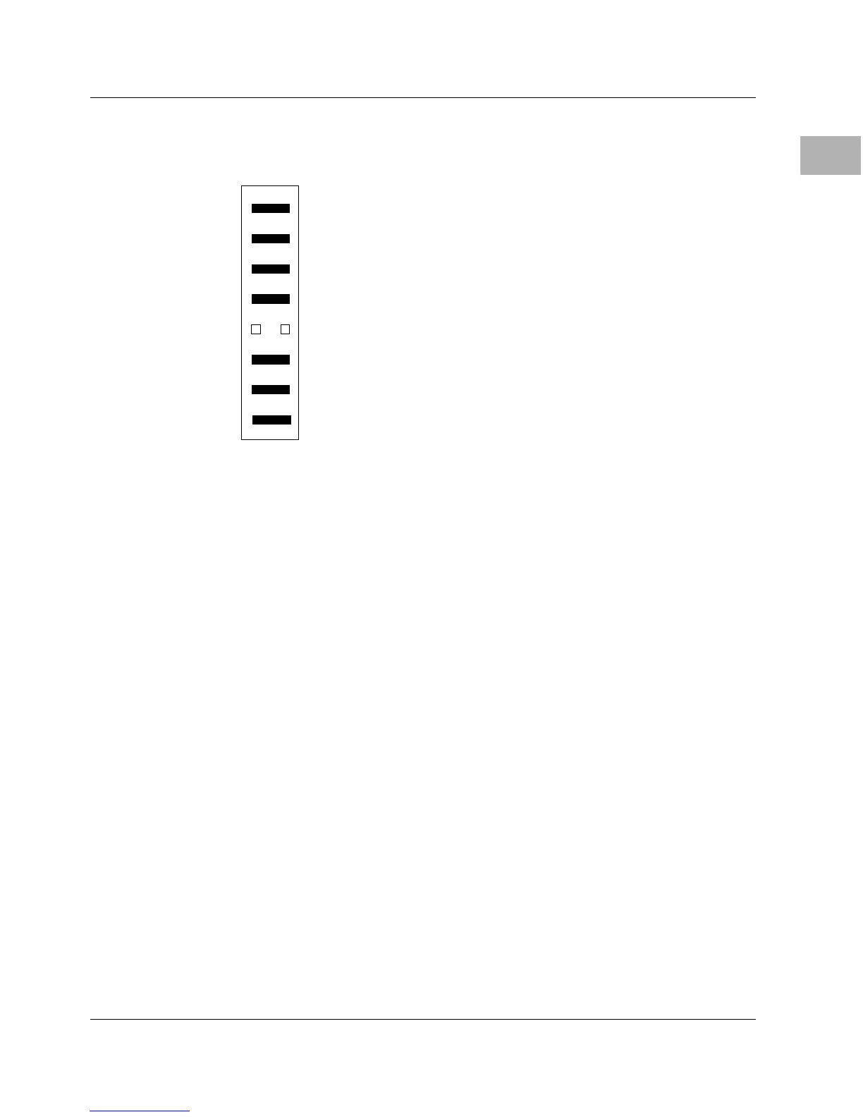
The 700/800-series MVME162LX has two 100-pin connectors (J15
and J22) to accommodate optional memory mezzanine boards. Two
memory mezzanine options are available:
❏ 4/8/16MB parity DRAM
❏ 4/8/16/32MB ECC DRAM
The mezzanine boards may either be used individually or be
combined in a stack (not more than two deep). The following
connector options govern stacking arrangements:
❏ The 4/8/16MB parity DRAM board has connectors on the
bottom only; it must be either the only mezzanine or the top
mezzanine.
❏ All ECC DRAM boards have two connector options:
– Connectors top and bottom for stackability
– Connectors on the bottom only; must be either the only
mezzanine or the top mezzanine
J21
15
GPI0
GPI1
GPI2
GPI6
GPI3
GPI4
GPI5
12
16GPI7
EPROMs Selected (factory configuration except on no-VMEbus models)
REFER TO 162BUG MANUAL
REFER TO 162BUG MANUAL
REFER TO 162BUG MANUAL
USER-DEFINABLE
IN=FLASH; OUT=EPROM
USER-DEFINABLE
USER-DEFINABLE
USER-DEFINABLE
162BUG INSTALLED
USER-DEFINABLE
USER-DEFINABLE
USER-DEFINABLE
USER-DEFINABLE
IN=FLASH; OUT=EPROM
USER-DEFINABLE
USER-DEFINABLE
USER-DEFINABLE
USER CODE INSTALLED
78

 Loading...


