Installation Instructions
2-15
2
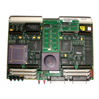
IP Installation on the MVME162LX
Up to two IPs may be installed on the 700/800-series MVME162LX.
Install the IPs on the board as follows:
1. Each IP has two 50-pin connectors that plug into two
corresponding 50-pin connectors on the MVME162LX: J5/J6,
J7/J8. See Figure 2-1 for the MVME162LX connector
locations.
– Orient the IP(s) so that the tapered connector shells mate
properly. Plug IP_a into connectors J5 and J6; plug IP_b
into J7 and J8. If a double-sized IP is used, plug IP_ab into
J5, J6, J7, and J8.
2. Two additional 50-pin connectors (J3 and J4) are provided
behind the MVME162LX front panel for external cabling
connections to the IP modules. There is a one-to-one
correspondence between the signals on the cabling
connectors and the signals on the associated IP connectors
(i.e., J4 has the same IP_a signals as J5; J3 has the same IP_b
signals as J7).
– Connect user-supplied 50-pin cables to J3 and J4 as
needed. Because of the varying requirements for each
different kind of IP, Motorola does not supply these cables.
– Bring the IP cables out the narrow slot in the MVME162LX
front panel and attach them to the appropriate external
equipment, depending on the nature of the particular
IP(s).

 Loading...