2-8
Hardware Preparation and Installation
2
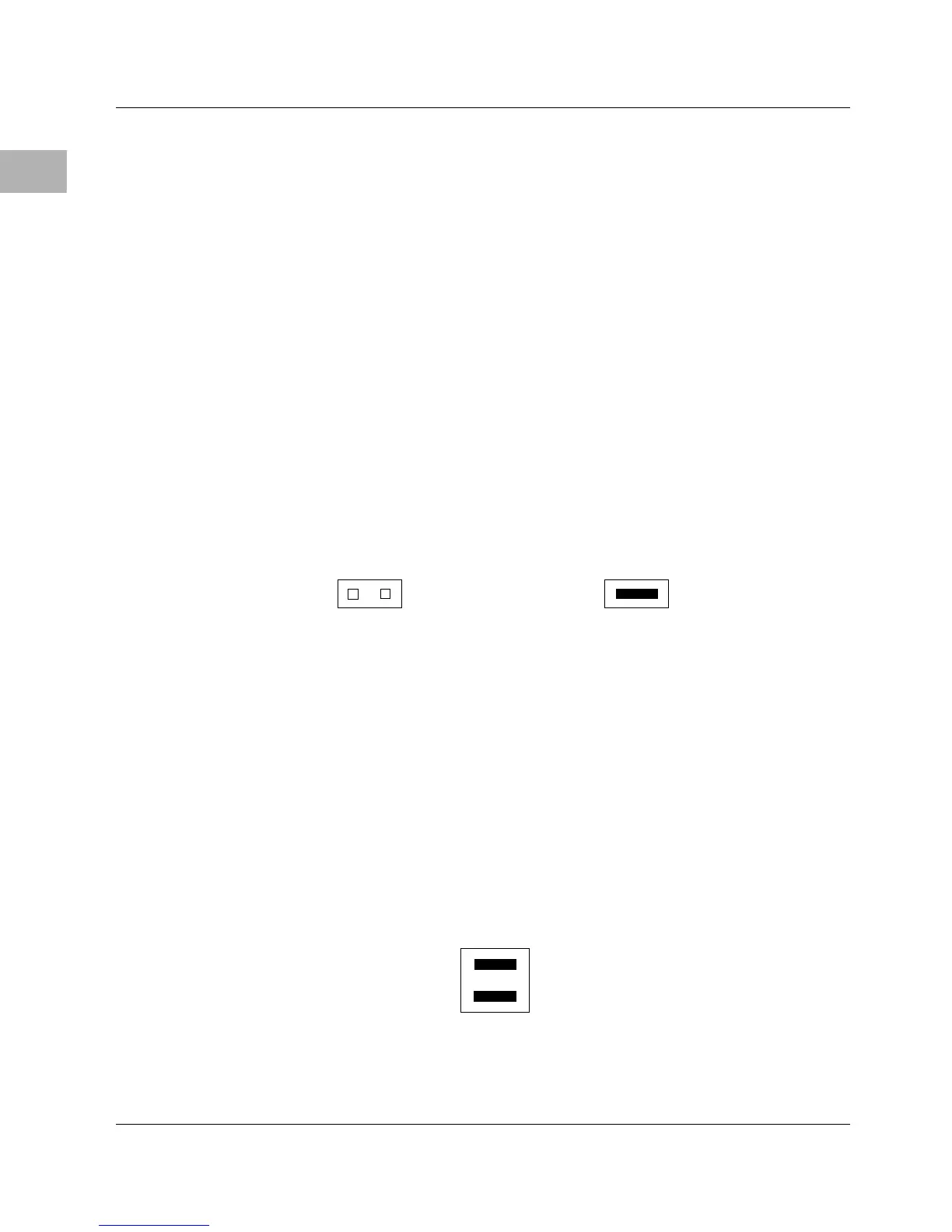
IP Bus Strobe Select Header (J18)
Some IP bus implementations make use of the Strobe∗ signal (pin
46) as an input to the IP modules from the IP2 chip. Other IP
interfaces require that the strobe be disconnected.
With a jumper installed between J18 pins 1 and 2, a programmable
frequency source is connected to the Strobe∗ signal on the IP bus
(for details, refer to the IP2 chip programming model in the
MVME162LX Embedded Controller Programmer’s Reference Guide).
If the jumper is removed from J18, the strobe line is available for a
sideband type of messaging between IP modules. The Strobe∗
signal is not connected to any active devices on the board, but it
may be connected to a pull-up resistor.
IP DMA Snoop Control Header (J19)
The jumpers on header J19 define the state of the snoop control bus
when an IP DMA controller is local bus master. Placing a jumper on
J19 pins 3 to 4 inhibits snooping (the snoop signal to the MC68040
is driven low during IP DMA). Leaving pins 3 and 4 unconnected
enables snooping. Pins 1 and 2 are not used for the MC68040.
1212
J18
IP Strobe disconnected
(Factory configuration)
J18
IP Strobe connected
J19
Snoop Inhibited
34
12
(Factory configuration)

 Loading...


