2-12
Hardware Preparation and Installation
2
General-Purpose Readable Jumpers Header (J21)
Header J21 provides eight readable jumpers. These jumpers are
read as a register (at $FFF4202D) in the MC2chip LCSR (local
control/status register). The bit values are read as a 0 when the
jumper is installed, and as a 1 when the jumper is removed.
With the factory-installed MVME162BUG firmware in place, four
jumpers are user-definable (pins 9-10, 11-12, 13-14, 15-16). If the
MVME162BUG firmware is removed, seven jumpers are user-
definable (i.e., pins 1-2, 3-4, 5-6, 9-10, 11-12, 13-14, 15-16).
Note Pins 7-8 (GPI3) are reserved to select either the Flash
memory map (jumper installed) or the EPROM
memory map (jumper removed). They are not user-
definable. The address ranges for the various
EPROM/Flash configurations appear in the section on
header J20.
In most cases, the MVME162LX is shipped from the factory with J21
set to all zeros (jumpers on all pins) except for GPI3 (pins 7-8). On
boards built with the no-VMEbus option, however, GPI3 is jumpered
as well.
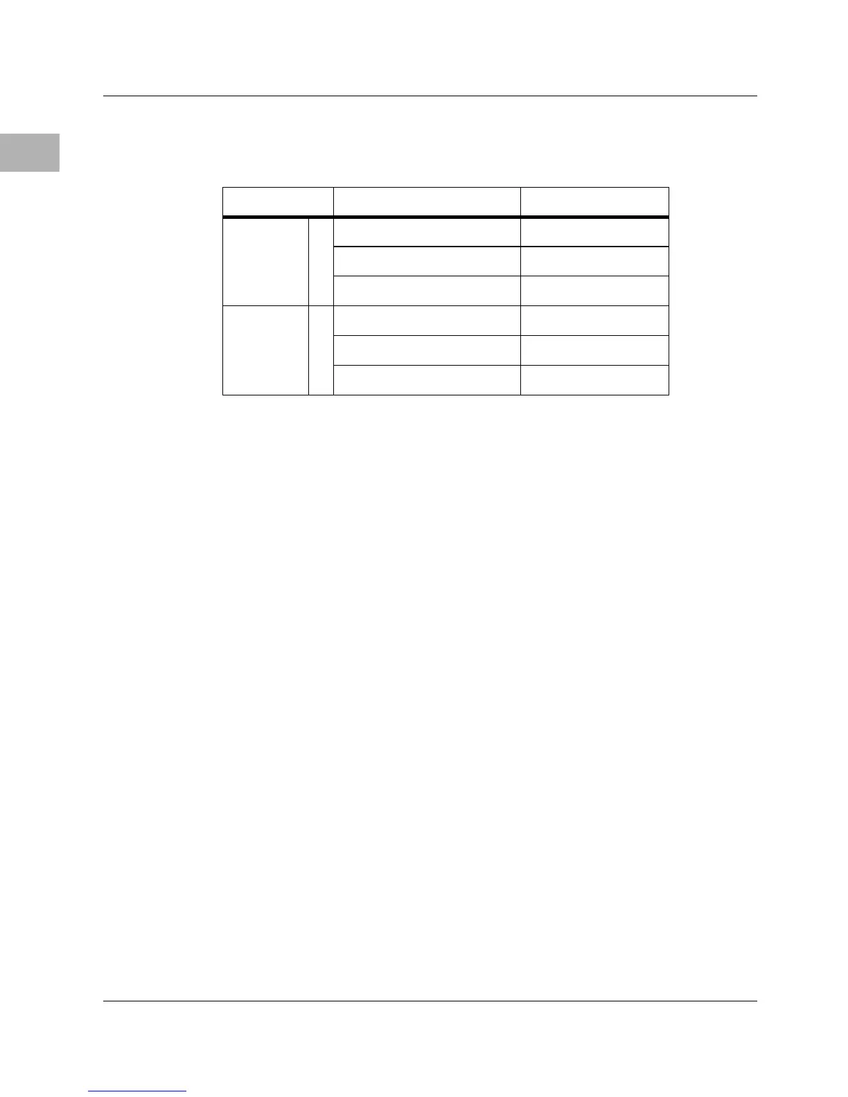
Table 2-6. EPROM/Flash Mapping — 1M x 8 EPROMs, Onboard Flash
Disabled
GPI3 Address Range Device Accessed
Removed 1 $FF800000 - $FF8FFFFF EPROM A (XU1)
$FF900000 - $FF9FFFFF EPROM B (XU2)
Not used Onboard Flash
Installed 0 Not used Onboard Flash
$FF800000 - $FF8FFFFF EPROM A (XU1)
$FF900000 - $FF9FFFFF EPROM B (XU2)

 Loading...


