ROMboot
3-9
3
ROMboot
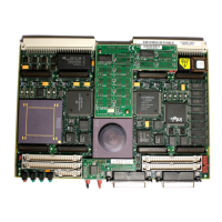
As shipped from the factory, 162Bug occupies an EPROM installed
in socket XU2. This leaves one socket (XU1) and the Flash memory
available for your use. Contact your Motorola sales office for
assistance. This function is configured/enabled by the
Environment (
ENV) command (refer to Appendix A) and executed
at powerup (optionally also at reset) or by the
RB command
assuming there is valid code in the memory devices (or optionally
elsewhere on the board or VMEbus) to support it. If ROMboot code
is installed, a user-written routine is given control (if the routine
meets the format requirements). One use of ROMboot might be
resetting SYSFAIL* on an unintelligent controller module. The
NORB command disables the function.
For a user's ROMboot module to gain control through the ROMboot
linkage, four requirements must be met:
❏ Power must have just been applied (but the ENV command
can change this to also respond to any reset).
❏ Your routine must be located within the MVME162LX
Flash/PROM memory map (but the
ENV command can
change this to any other portion of the onboard memory, or
even offboard VMEbus memory).
❏ The ASCII string ‘‘BOOT’’ must be located within the
specified memory range.
❏ Your routine must pass a checksum test, which ensures that
this routine was really intended to receive control at
powerup.
For complete details on how to use ROMboot, refer to theDebugging
Package for Motorola 68K CISC CPUs User's Manual.
