EasyManuals Logo

Motorola 700 Series User Manual

Motorola 700 Series
156 pages
To Next Page IconTo Next Page
To Previous Page IconTo Previous Page
Page #58 background imageLoading...
Page #58 background image
2-10
Hardware Preparation and Installation
2
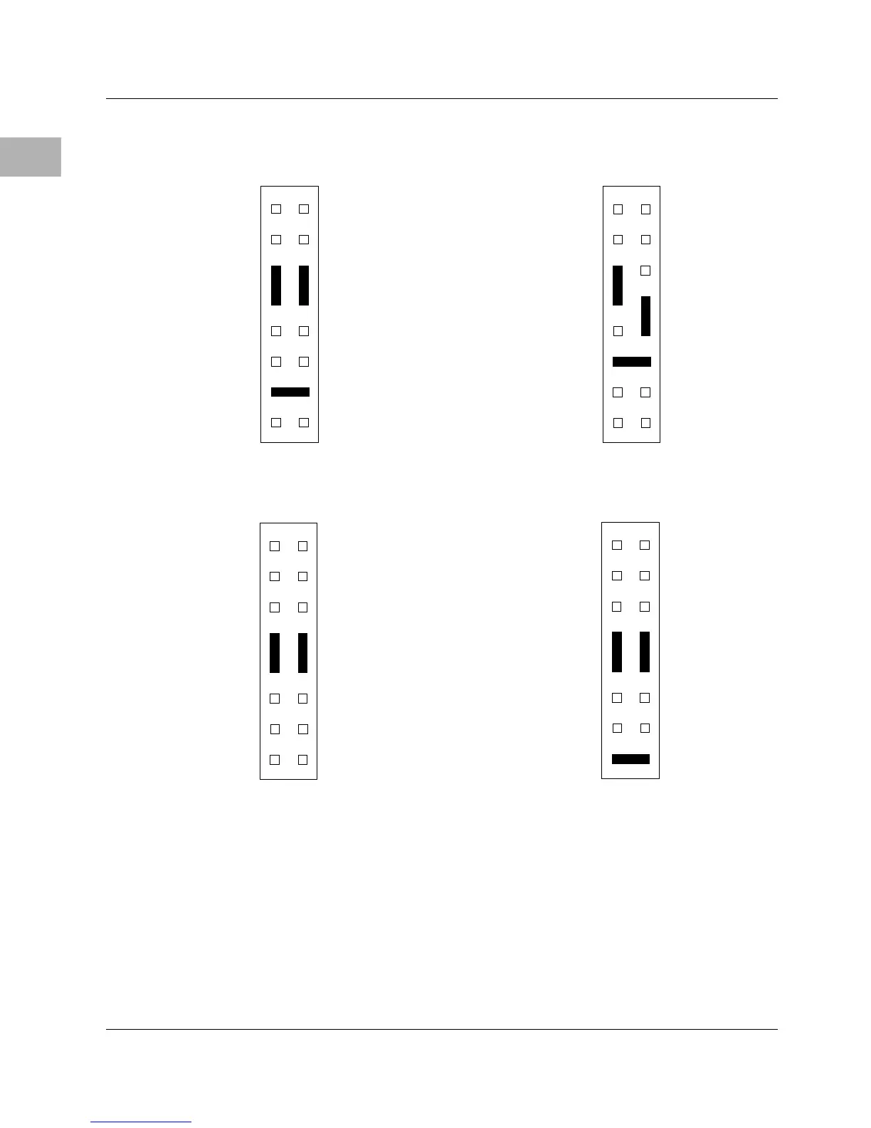
The next four tables show the address range for each EPROM socket
in all four configurations. GPI3 (J21 pins 7-8) is a control bit in the
MC2chip ASIC that determines whether reset code is fetched from
Flash memory or from EPROMs.
J20
15
12
16
CONFIGURATION 4: 1M x 8 EPROMs
ONBOARD FLASH DISABLED
J20
15
12
16
CONFIGURATION 3: 1M x 8 EPROMs
J20
15
12
16
CONFIGURATION 2: 512K x 8 EPROMs
J20
15
12
16
CONFIGURATION 1: 256K x 8 EPROMs
(FACTORY DEFAULT)

Table of Contents

Questions and Answers:

Question and Answer IconNeed help?

Do you have a question about the Motorola 700 Series and is the answer not in the manual?

Motorola 700 Series Specifications

General IconGeneral
BrandMotorola
Model700 Series
CategoryController
LanguageEnglish

Related product manuals