Installation: Remote Control Installation
16 6881086C22-B
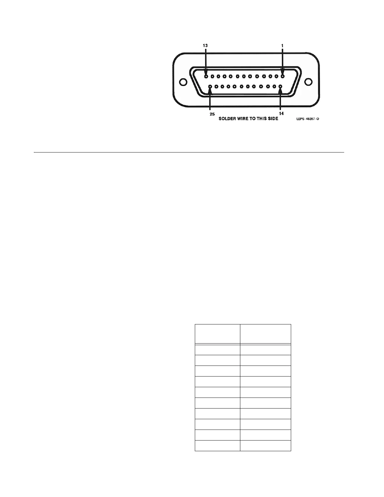
Figure 4. Accessory 2 and 3 Mating Connector
Remote Control
Installation
Digital Remote Control
Installation
This procedure is to be used for installation of the RCH3000 or MC3000 digital
remote deskset. Make sure switches 1 and 7 of S101 on the audio interface
board are in the ON position. Refer to the digital remote deskset manual for
information regarding deskset operation. Table 10 lists the Accessory
Connector 2 pins used for Digital Remote Control operation.
NOTES: All information, such as mode names, phone lists, call lists,
and message names should be programmed in the ASTRO
radio using Customer Programming Software (CPS).
External Alarms (Horn and Lights): The Consolette routes
the VIP lines from the local control head in W7 models to the
rear accessory connector of the Consolette for the External
Alarm feature. Access to the VIP lines in W9 models is at the
remote deskset. Consult the MC3000 manual for detailed
information concerning configuration and support.
Table 10. Accessory Connector 2 Pins: Digital Remote Control Operation
Pin
Number
Signal Name
2 AUD_SHLD
3TX+
6BUSY
7BUS+
11 TX–
12 DIG_GND
14 REMOTE_RX+
15 REMOTE_RX–
19 BUS–
20 RESET
 Loading...


