Maintenance: Disassembly and Reassembly
6881086C22-B 41
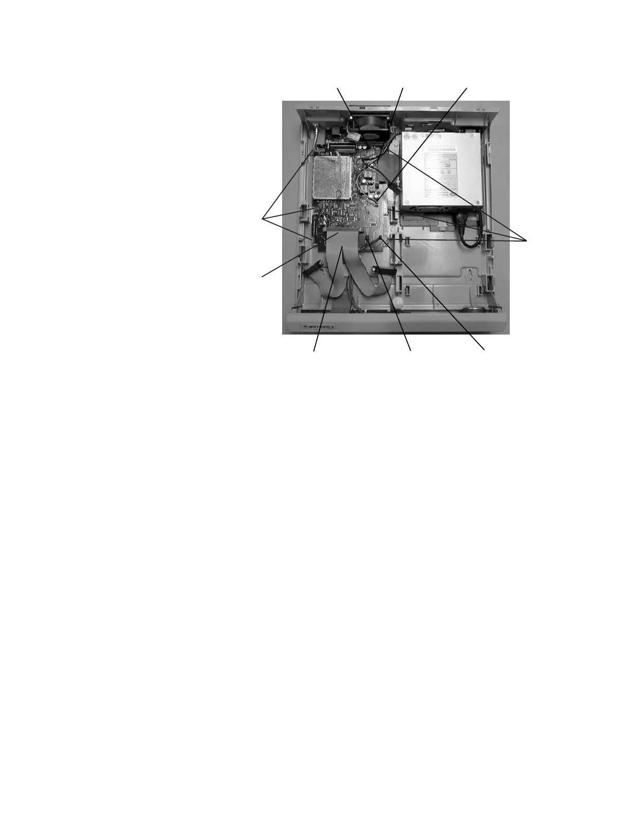
Figure 15. Removing the AIB/TRC Board
Replacing the AIB/TRC
Board
1. Insert the AIB/TRC board into the Consolette housing and snap it into
place. When inserting the TRC into the Consolette housing, make sure
that the board is secured by the two retainers to the right and left of the
opening for Accessory Connector 1.
2. Connect the accessory cable to connector J3 on the AIB/TRC board.
3. Connect the transceiver cable to connector J1 on the AIB/TRC board.
4. Connect the power cable to connector J11 on the AIB/TRC board.
5. Connect the power LED cable to connector J5 on the AIB/TRC board.
6. Connect the fan cable to connector J8 (AIB) or J13 (TRC).
7. Connect the control head cable TRN7393 to connector J2 on the AIB/TRC
board. (This cable is only present on the Local Control (W7) Consolettes.)
8. Connect the speaker cable to connector J4 on the AIB/TRC board. (This
cable is only present on the Local Control (W7) Consolettes.)
9. Connect the cable for the Clock/VU meter to J6 on the AIB/TRC board, if
the option is present.
NOTE: The emergency battery revert option is no longer supported
by Rev C and higher versions of the AIB and TRC boards.
10.Perform the steps for replacing the ASTRO Transceiver (see “Replacing
the Transceiver” on page 40).
Control Head Cable
(Underneath the
Transceiver Cable)
Power LED
Cable
Speaker
Cable
Power
Cable
Accessory
Cable
Fan
Cable
Retainer
Snaps
Retainer
Snaps
Transceiver
Cable
 Loading...


