Network Settings
15
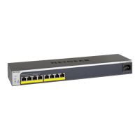
ProSAFE Easy-Mount 8-Port Gigabit Ethernet PoE+ Web Managed Switch
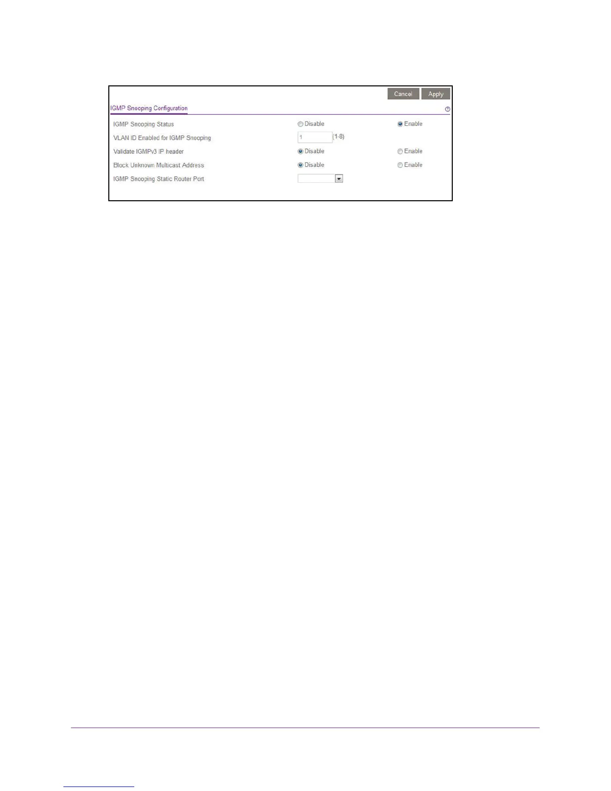
6. Make sure that the IGMP Snooping Status Enable radio button is selected.
By default, the Enable radio button is selected.
7. (Optional) Select the Validate IGMPv3 IP header Enable radio button.
Some network devices might not conform to the IGMPv3 standard. When the Validate
IGMPv3 IP header option is enabled, IGMP messages are required to include TTL = 1
and ToS Byte = 0xC0 (Internetwork Control), and the router alert IP option (9404) must
be set. Otherwise, the packets are ignored.
8. (Optional) Select the Block Unknown MultiCast Address Enable radio button.
When this feature is enabled, multicast packets are forwarded only to the ports that are in
the multicast group learned from IGMP snooping. All unknown multicast packets are
dropped.
9. (Optional) Select any item in the IGMP Snooping Static Router Port menu.
You can select a port to be the dedicated IGMP snooping static router port if no IGMP
query exists in the network for the switch to discover the router port dynamically. After a
port is selected as the static router port, all IGMP Join and Leave reports are forwarded to
this port.
10. Click the Apply button.
Your settings are saved.
Specify a VLAN for IGMP Snooping
To specify a VLAN for IGMP snooping:
1. Connect your computer to the same network as the switch.
You can use a WiFi or wired network connection, or connect directly to a switch that is
off-network using an Ethernet cable.
2. Launch a web browser.
3. In the address field of your web browser, enter the IP address of the switch.
If you do not know the IP address of the switch, see Access the Switch Using a Web
Browser on page 6.
The login window opens.
 Loading...