SECTION 3 -- FIELD OPERATIONS
3--30
REMOTE CONTROL VALVES
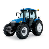
QUICK--FIT COUPLERS -- Fig. 40
One, two or three control valves (which use the same
oil circuit as the hydraulic lift), can be fitted to your
tractor for remote control of single--acting and
double--acting cylinders.
Each valve has two slide lock type female
1
/
2
in.
couplers which can be connected with pressurised
male couplers. You can thus connect the control
cylinder lines with two hands.
WARNING
The couplers have no breakaway capability with the
hoses in them.
Valves and their colours are shown at Figures: 40
and 43.
Valve no:
Colour
1. Green
2. Blue
3. Brown
Remote outlets shown in Fig. 40 on left side (line B)
is used to retract the cylinder, on right side (line A) is
used to extend the cylinder.
Before fitting and releasing the hoses, first slide the
collar of female couplers, but only after first:
-- switching off the engine;
-- lowering any implements connected to the lift;
-- thoroughly cleaning the two parts to be
connected.
WARNING
When not using the female couplers, protect them
with plastic caps (A) fig. 40.
A
1
2
3
B
C
TRE0854A
40
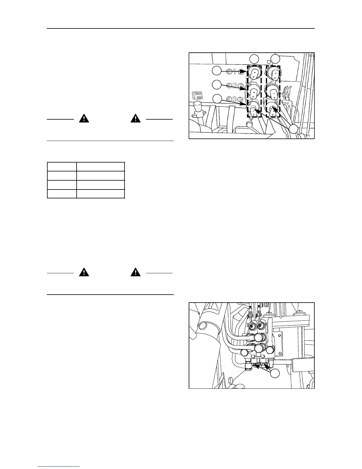
SINGLE--ACTING/DOUBLE--ACTING
SWITCHING -- Fig. 41
To switch the control valves to:
-- Single--acting, slacken screw (1) fig. 41 near to
the valve control lever pivot until it stops.
-- Double --acting, fully tighten (1) fig. 41.
When using single acting, in order to accelerate the
identification of the coupler to which the implement
is to be connected, actuate the valve lever and
observe the two lines to which the couplers are
connected: the line carrying the oil should move.
For greater safety, check that the line to which the
implement connected using single acting is on the
valve body that connected furthest from the change
over screw.
1
TRE0824A
41
 Loading...