ENGLISH – 11
TESTING AND COMMISSIONING
5
5 TESTING AND COMMISSIONING
These are the most important phases of the automation’s con-
struction, as they ensure maximum safety of the system. The
test can also be used to periodically verify the devices making
up the automation.
Testing and commissioning of the automation must be per-
formed by skilled and qualied personnel, who are responsible
for the tests required to verify the solutions adopted according
to the risks present, and for ensuring that all legal provisions,
standards and regulations are met, in particular all the require-
ments of the EN 12445 standard, which denes the test meth-
ods for checking gate automations.
The additional devices must undergo specic testing, both in
terms of their functions and their proper interaction with the con-
trol unit. Refer to the instruction manuals of the individual devic-
es.
5.1 TESTING
The sequence of steps to be performed when running the test-
ing phase, as described below, refers to a typical system (“Fig-
ure 3”).
To run the test:
1. check that the activation of the STEP-BY-STEP (Sbs) input
triggers the “Open, Stop, Close, Stop” sequence
2. check that the activation of the AUX input (Type 1 partial
opening function) manages the “Open, Stop, Close, Stop”
sequence only for the upper leaf motor. The lower leaf mo-
tor must remain still during the closing phase
3. start an opening manoeuvre and verify that:
– when engaging FOTO (PHOTO) the gate continues the
opening manoeuvre
– when engaging FOTO1 (PHOTO1) the manoeuvre
stops until FOTO1 is disengaged. Subsequently, the
manoeuvre will resume the opening movement
– with FOTO2 (PHOTO2), after engaging this device, the
manoeuvre must stop and restart during the closing
phase
4. verify that when the leaf reaches the mechanical stop for
the opening phase, the motors switch off
5. start a closing manoeuvre and verify that:
– when engaging FOTO, the manoeuvre stops and re-
starts during the opening phase
– when engaging FOTO1 (PHOTO1) the manoeuvre
stops until FOTO1 is disengaged. Subsequently, the
manoeuvre will resume the opening movement
– when engaging FOTO2, the gate continues the closing
manoeuvre
6. verify that the stoppage devices connected to the STOP
input cause the immediate stoppage of any movement un-
der way and a brief reversal
7. check that the level of the obstacle detection system is
suited to the application: during the manoeuvre, during
both the opening and closing phases, prevent the leaf’s
movement by simulating an obstacle and verify that the
manoeuvre reverses before exceeding the force specied
in the regulations
8. other checks can be necessary depending on the devices
connected to the inputs.
a
If an obstacle is detected for two consecutive ma-
noeuvres in the same direction, the control unit will
perform a partial reversal of both motors for one
second only. After the next command is given, the
leaves will start opening and the rst intervention of
the amperometric device for each motor will be re-
garded as a mechanical stop for the opening phase.
The same behaviour occurs when the mains power
supply is restored: the rst command is always an
opening command and the rst obstacle is always
regarded as a mechanical stop for the opening
phase.
5.2 COMMISSIONING
a
Commissioning can only be performed after all test-
ing phases have been successfully completed.
a
Before commissioning the automation, ensure that
the owner is properly informed of all residual risks
and hazards.
To commission the automation:
1. compile the automation’s technical le, which must in-
clude the following documents: overall drawing of the
automation, wiring diagram, risk assessment and relative
solutions adopted, the manufacturer’s declaration of con-
formity for all devices used and the declaration of con-
formity compiled by the installer
2. afx a data plate on the gate specifying at least the fol-
lowing data: type of automation, name and address of
the manufacturer (responsible for commissioning), serial
number, year of manufacture and CE mark
3. compile the declaration of conformity of the automation
and hand it to the owner of the automation
4. compile the User Manual of the automation and hand it to
the owner of the automation
5. compile and provide the owner with the automation’s
“Maintenance schedule”, containing the maintenance in-
structions for all the automation’s devices.
l
For all the above-mentioned documentation, Nice –
through its technical assistance service – provides
the following: pre-completed forms.
PROGRAMMING
6
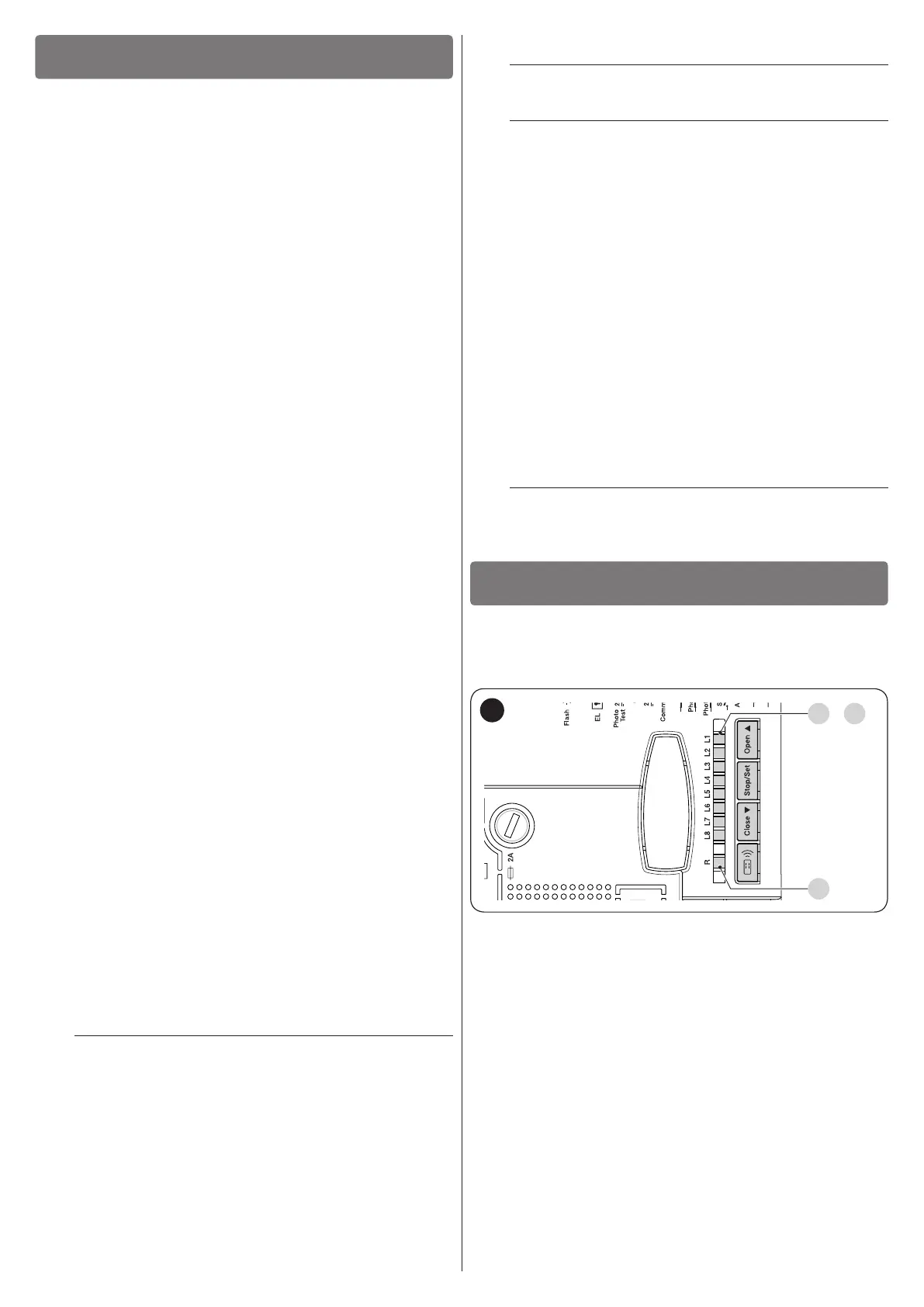
6 PROGRAMMING
There are 4 buttons on the control unit: [Open
p
], [Stop/Set],
[Close
q
] and [Radio
R
] (“Figure 21”), which can be used
both for commanding the control unit during the testing phases
and for programming the available functions.
L1 L8
..
LR
21
The programmable functions available are arranged on two lev-
els and their operating status is signalled by the eight LEDs “L1
... L8” and by the “LR” LED present on the control unit (LED lit =
function active; LED off = function not active).
6.1 USING THE PROGRAMMING BUTTONS
[Open
p
]:
– Button for commanding the gate opening
– Selection button during the programming phase.
[Stop/Set]:
– Button used to stop a manoeuvre
– If pressed for more than 5 seconds, it allows for entering the
programming mode.
[Close
q
]
– Button for commanding the gate’s closure
– Selection button during the programming phase.

 Loading...


