8 – ENGLISH
4.2.4 Notes on connections
Most of the connections are extremely easy to make, as they are
largely connections directed at a single user or contact. Below
are some examples on how to connect external devices.
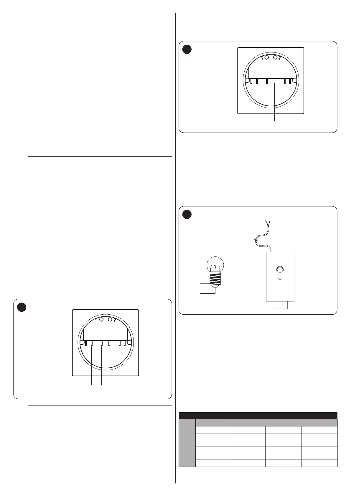
4.2.4.1 Stand-by all / Phototest connection
The “Stand-by all” function allows for reducing consumption and
is active as a standard feature. It is automatically excluded only
when the “Phototest” function activates.
Note The “Stand-by all” and “Phototest” functions are alterna-
tive, as one excludes the other.
The possible connection options are listed below:
– with “Stand-by all” active (energy saving) (“Figure 7 A”)
– without “Stand-by all” and without “Phototest” (standard con-
nection) (“Figure 7 B”)
– without “Stand-by all” and with “Phototest” (“Figure 7 C”).
With the “Stand-by all” function active, 1 minute after the end of
the manoeuvre the control unit enters the “Stand-by all” mode
by switching off all the inputs and outputs to limit consumption.
The relevant status is signalled by the “OK” LED, which starts
ashing more slowly.
m
If the control unit is powered with a photovoltaic
panel (“Solemyo” system) or with a back-up bat-
tery, the “Stand-by all” function must be activated
as shown in the “energy saving” diagram (“Figure
7 A”).
When the “Stand-by all” function is not required, the “Phototest”
function can be activated, which can be used to verify – at the
start of each manoeuvre – whether the connected photocells are
working properly. To use this function, it is necessary to connect
the photocells appropriately (“Figure 7 C”) and then activate
the function.
Note By activating the “Phototest” function, the inputs sub-
ject to the testing procedure are PHOTO, PHOTO1 and
PHOTO2. If one of these inputs is not used, it must be
connected to the “PHOTOTEST” terminal (number 5)
("Figure 7 D").
4.2.4.2 Key selector connection
Connection of the key selector to perform the “STEP-BY-STEP”
and “STOP” functions (“Figure 9”).
STEP BY STEP
NC NCNO NOC C
12 8 8 9
ALT
9
m
To connect ALT (STOP) with the “Stand-by all” func-
tion active, use terminal no. 5 and not no. 8 (see the
“Stand-by all / Phototest connection” paragraph).
Connection of the selector to carry out the “STEP-BY-STEP”
functions and one of those relevant to the AUX auxiliary input
(PARTIAL OPENING, OPEN ONLY, CLOSE ONLY, etc.) (“Fig-
ure 10”).
STEP BY STEP
12 8 8 13
AUX
NC NCNO NOC C
10
4.2.4.3 Connecting the Open Gate Indicator / Electric
Lock
The OGI (Open Gate Indicator) output, if suitably programmed,
can be used as a “Open Gate Indicator”. The indicator light
will ash slowly during the opening phase and quickly during
the closing phase. It will remain steady lit with the gate open
(stopped) and off with the gate closed. If the output is pro-
grammed as an electric lock, it activates for 3 seconds whenev-
er an opening manoeuvre starts (“Figure 11”).
OGI
33Vc
max 5 W
12Va
max 15 VA
EL
3
3 4
4
11
4.2.5 ALT (STOP) input type
The MC424L control unit can be programmed to congure two
types of ALT (STOP) inputs:
– NC-type STOP for NC contacts
– Fixed resistor STOP type for connecting devices with 8.2 kΩ
xed resistor output (e.g. sensitive edges) to the control unit.
The input measures the resistor’s value and removes the ma-
noeuvre consent when the resistor exceeds the nominal val-
ue. With suitable arrangements, normally open (NO), normally
closed (NC) and even multiple devices of a different type can
be connected to the ALT input, congured as a xed resistor
(see “Table 3”).
Table 3
FIXED RESISTOR STOP INPUT
SECOND device
type
FIRST device type
NO NC 8.2 kΩ
NO
In parallel
[Note 1]
[Note 2]
In parallel
NC [Note 2]
In series
[Note 3]
In series
8.2 kΩ
In parallel In series
[Note 4]

 Loading...


