ENGLISH – 7
4.2.2 Description of connections
The meaning of the codes/wording stamped on the electronic board near the relative terminals is described below.
Table 1
ELECTRICAL CONNECTIONS
Terminals Function Description Cable type
120/230/250 V ~ 50/60
Hz POWER SUPPLY
Mains power supply 3 x 1.5 mm
2
Motor 1
Connection of motor M1 [note 1]
3 x 1.5 mm
2
Motor 2 Connection of motor M2 3 x 1.5 mm
2
1÷2
Warning light
Connection of the 24 V c max 25 W warning light
2 x 1 mm
2
3÷4
OGI / Electric lock
Connection of the 24 V c max 5 W Open Gate Indicator or 12 V c max 15
VA Electric Lock (see the “PROGRAMMING” chapter)
OGI: 2 x 0.5 mm
2
Electric lock: 2 x 1
mm
2
5
24 V c common
input (with Stand-by
all / phototest)
+24 V c power supply for TX photocells with phototest (max 100 mA);
“COMMON” for all safety inputs, with “Stand-by all” function active [note 2]
1 x 0.5 mm
2
6 0 V c 0 V power supply c for services
1 x 0.5 mm
2
7 24 V c Services power supply, without “Stand-by all” (24 V c max 200 mA)
1 x 0.5 mm
2
8 Common 24 V c Common for all inputs (+24 V c) without “Stand-by all”
1 x 0.5 mm
2
9
ALT (STOP)
Input with STOP function (emergency, safety lock) [note 3]
1 x 0.5 mm
2
10
FOTO (PHOTO) NC input for safety devices (photocells, sensitive edges) 1 x 0.5 mm
2
11
FOTO1 (PHOTO1) NC input for safety devices (photocells, sensitive edges) 1 x 0.5 mm
2
12
PASSO-PASSO
(STEP-BY-STEP)
Input for cyclic operation (OPEN-STOP-CLOSE-STOP) 1 x 0.5 mm
2
13
AUX
Auxiliary input [note 4]
1 x 0.5 mm
2
Antenna Radio receiver antenna connection
RG58-type shielded
cable
Note 1 Not used for single-leaf gates (the control unit automatically recognises whether there is only one motor installed).
Note 2 The “Stand-by all” is used to limit consumption; for further details on the electrical connections, refer to the “Stand-by all /
Phototest connection” paragraph, and consult the “PROGRAMMING” chapter for information on programming.
Note 3 The ALT (STOP) input can be used for NC contacts or 8.2 kΩ xed resistor contacts in self-recognition mode (see the “
PROGRAMMING” chapter).
Note 4 The AUX auxiliary input is programmed by default with the “Type 1 partial open” function, but can be programmed with one
of the functions shown in “Table 2”.
Table 2
PROGRAMMABLE FUNCTIONS FOR THE AUX INPUT
Function Type of input Description
TYPE 1 PARTIAL OPEN
NO (normally open) Opens the upper leaf completely
TYPE 2 PARTIAL OPEN
NO (normally open) Opens the two leaves halfway
OPEN
NO (normally open) Performs the open manoeuvre only
CLOSE
NO (normally open) Performs the close manoeuvre only
PHOTO 2
NC (normally closed) PHOTO 2 function
STOP
NO (normally open) Stops the manoeuvre
EXCLUDED
-- No function
4.2.3 Operations for connection
To make the electrical connections (“Figure 7”):
1. remove the terminals from their housings
2. connect the various devices to the relevant terminals ac-
cording to the diagram shown in “Figure 7”
3. put the terminals back into their housings.
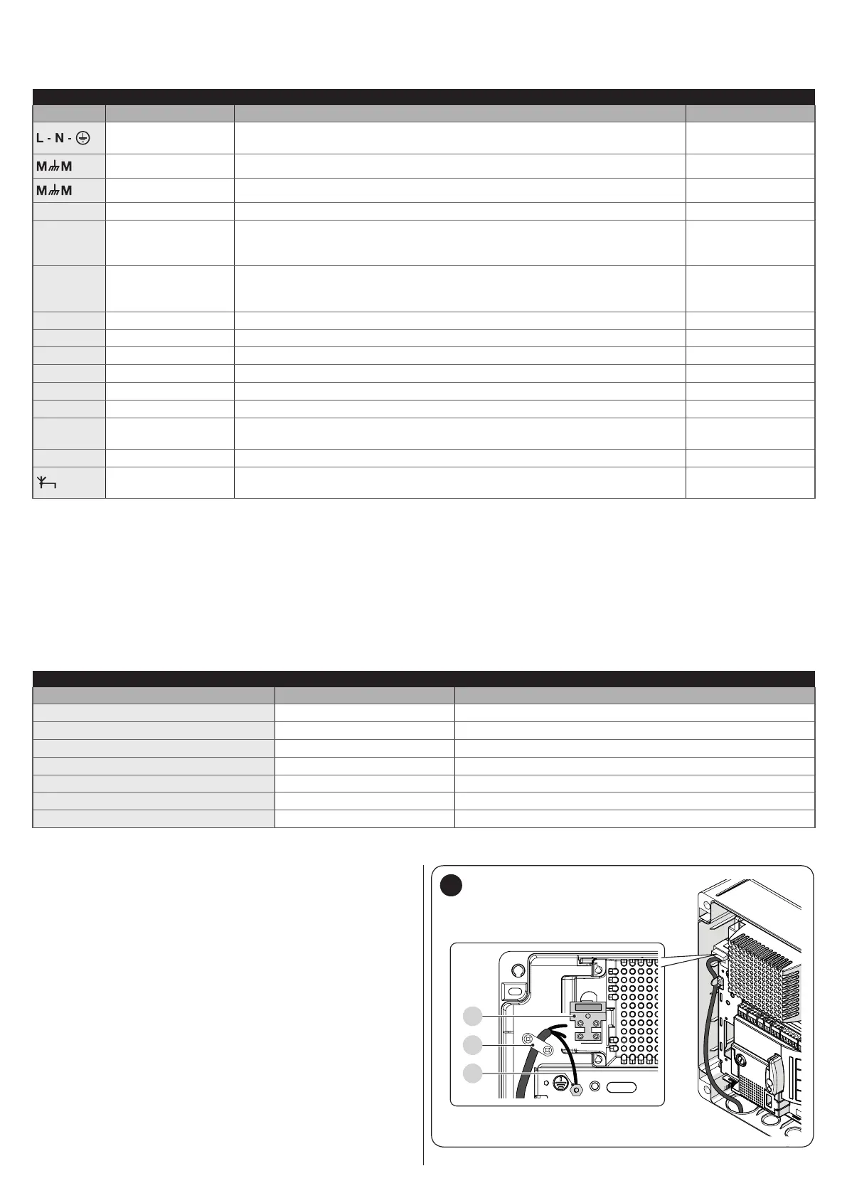
4. connect the power supply cable to points (A) and (B) and
secure it with the cable clamp (C) (“Figure 8”).
8

 Loading...


