4 – ENGLISH
INSTALLATION
3
3 INSTALLATION
3.1 PRE-INSTALLATION CHECKS
Before proceeding with the product’s installation, it is necessary
to:
– check the integrity of the supply
– check that all the materials are in good working order and
suited to the intended use
– check that all operating conditions comply with that specied
in the “Product usage limits” paragraph and in the “TECHNI-
CAL SPECIFICATIONS” chapter
– check that the chosen installation location is compatible with
the product’s overall dimensions (see “Figure 2”)
– check that the surface chosen for installing the product is sol-
id and can ensure stable attachment
– make sure that the installation area is not subject to ooding; if
necessary, the product must be installed appropriately raised
above ground level
– check that the space around the product allows safe and easy
access
– check that all electrical cables to be used belong to the type
listed in “Table 1”
– check that the automation has mechanical stops in both the
opening and closing phases.
3.2 PRODUCT USAGE LIMITS
The product must be used exclusively with WG2024, WG3524,
WG4024, WG5024, TOO3024, TOO4524, XME2024 gearmotors
and in accordance with the corresponding usage limits.
3.3 PRODUCT IDENTIFICATION AND OVERALL
DIMENSIONS
The overall dimensions and label (A) that allow for identifying the
product are shown in “Figure 2”.
232 mm
A
2
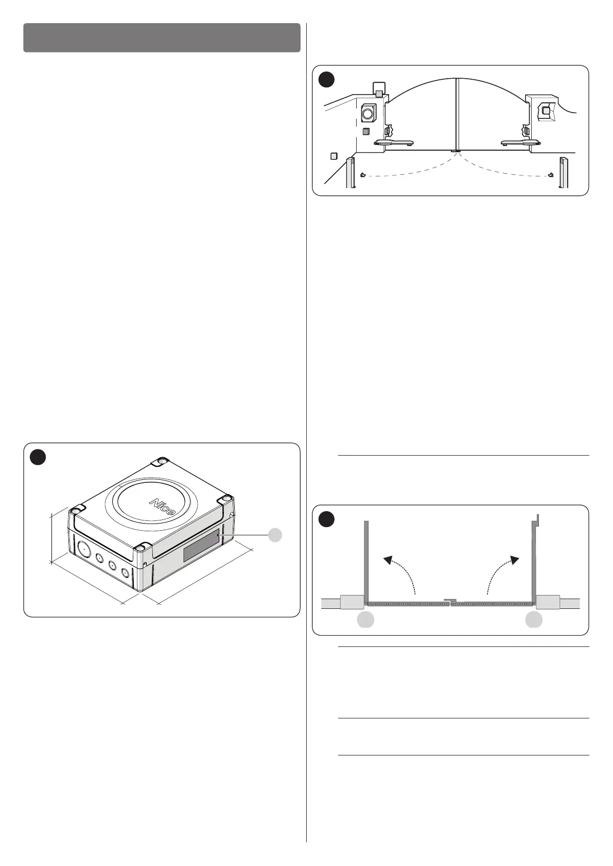
3.4 TYPICAL INSTALLATION
“Figure 3” shows an example of an automation system con-
structed using Nice components.
C
F F
D
E E
H
A
G
G
B
3
A WINGO, TOO, SFAB 24 V electro-mechanical actuator
B WINGO, TOO, SFAB 24 V electro-mechanical actuator
C Warning light
D Key selector
E “PHOTO” pair of photocells
F “PHOTO1” pair of photocells
G “PHOTO2” pair of photocells
H Control unit
These above-mentioned components are positioned according
to a typical standard layout.
In particular, bear in mind that:
– for the characteristics and connection of the photocells, con-
sult the specic instructions of the product
– the intervention of the “PHOTO” pair of photocells during the
opening phase has no effect, while it triggers a reversal during
the closing phase
– the intervention of the “PHOTO1” pair of photocells stops the
manoeuvre during both the opening and closing phases
– the intervention of the “PHOTO2” pair of photocells during the
closing phase (connected to the suitably congured AUX in-
put) has no effect, while it triggers a reversal during the open-
ing phase.
l
Bear in mind that motor M1 is the rst to start for
the closing movement, while motor M2 is the rst to
start for the opening movement (“Figure 4”).
M1 M2
4
a
Before proceeding with the installation, prepare the
electrical cables required for the system by refer-
ring to the “Wiring diagram and description of con-
nections” paragraph and to that specied in the “
TECHNICAL SPECIFICATIONS” chapter.
a
The cables used must be suited to the type of envi-
ronment of the installation site.
a
When laying the ducting for routing the electrical
cables and for the cable entry point into the control
unit housing, check that there are no water depos-
its in the junction wells nor condensate in the con-
nection ducts, as water and damp conditions could
damage the product’s electronic circuits.

 Loading...


