20 – ENGLISH
FURTHER INFORMATION
(Accessories)
8
8 FURTHER INFORMATION (Accessories)
8.1 CONNECTING AN SM-TYPE RADIO RECEIVER
The control unit has a slot for mounting radio receivers with SM
connector (optional accessories) belonging to the SMXI and
OXI families, which can be used to remotely control the control
unit through transmitters that intervene on the unit’s inputs.
f
Before installing a receiver, disconnect the power
supply to the control unit.
To install a receiver (“Figure 28”):
1. remove the cover of the control unit’s containment box
2. insert the receiver (A) in the appropriate slot (B) on the
control unit’s electronic board
3. put the cover of the control unit’s containment box back
on.
At this stage, the control unit can be powered again.
A
B
28
“Table 14” shows the receiver outputs and the control unit inputs
associated with each.
Table 14
SMXI / SMXIS OR OXI / OXIFM / OXIT / OXITFM IN MODE 1 OR MODE
2
Receiver output Control unit input
Output No. 1
Step-by-Step
Output No. 2
AUX (pre-set value: Partial open 1)
Output No. 3
“Open Only”
Output No. 4
“Close Only”
l
For further information, consult the specic manual
of the receiver.
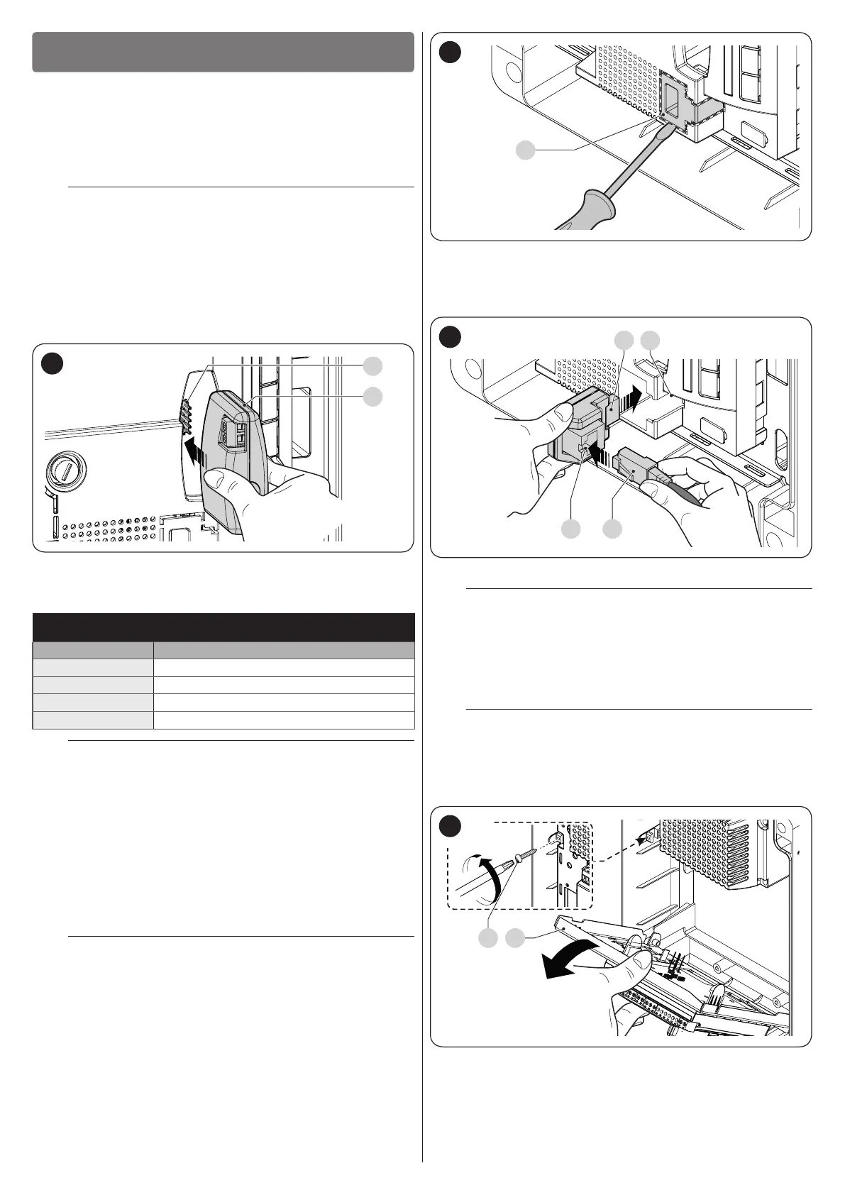
8.2 CONNECTING THE IBT4N INTERFACE
The control unit is equipped with a “IBT4N”-type connector for
the IBT4N interface, which allows for connecting all devices
equipped with BusT4 interface, such as, for example, Oview
programmers and the IT4WIFI Wi-Fi interface.
The Oview programmer allows for comprehensively and rapidly
managing the installation, maintenance and diagnosis of the en-
tire automated system.
f
Before connecting the interface, disconnect the
power supply to the control unit.
To install the interface (“Figure 29” and “Figure 30”):
1. remove the cover of the control unit’s containment box
2. remove the plastic pre-cut element (A) and check that
there are no burrs
29
3. place the interface (B) in the appropriate slot (C) on the
control unit’s electronic board
4. insert the cable (D) in the appropriate slot (E) on the in-
terface.
B C
DE
30
At this stage, the control unit can be powered again.
l
For further information, consult the specic manu-
als of the connected devices.
8.3 CONNECTING THE PS124 BACK-UP BATTERY
The control unit is congured for being powered with PS124
back-up batteries that intervene in case of a power outage.
f
Before installing a back-up battery, disconnect the
power supply to the control unit.
Before installing and connecting the back-up battery:
1. remove the cover of the control unit’s containment box
2. loosen the screw (A) and turn the panel (B)
A B
31

 Loading...


