ENGLISH – 9
Note 1 One or more NO devices can be connected in parallel
to one another without any quantity limitation with an 8.2
kΩ termination resistor (“Figure 12”). For electrical con-
nections with the “Stand-by all” function active, refer to
the “Stand-by all / Phototest connection” paragraph.
m
To connect ALT (STOP) with the “Stand-by all” func-
tion active, use terminal no. 5 and not no. 8 (see the
“Stand-by all / Phototest connection” paragraph).
12
Note 2 Multiple devices can be connected as NO and NC con-
tacts in parallel, taking care to place a 8.2 kΩ resistor in
series with the NC contact (this also allows for combin-
ing 3 devices: NO, NC and 8.2 kΩ (“Figure 13”).
13
Note 3 One or more NC-type devices can be connected in se-
ries to one another and to an 8.2 kΩ resistor without any
quantity limitation (“Figure 14”).
14
Note 4 Only one device with 8.2 kΩ xed resistor output can
be connected; if needed, multiple devices must be con-
nected “in cascade” mode with a single 8.2 kΩ termina-
tion resistor (“Figure 15”).
8
9
1 2
Sensitive
edge
Sensitive
edge
Sensitive
edge
n
8,2kΩ
15
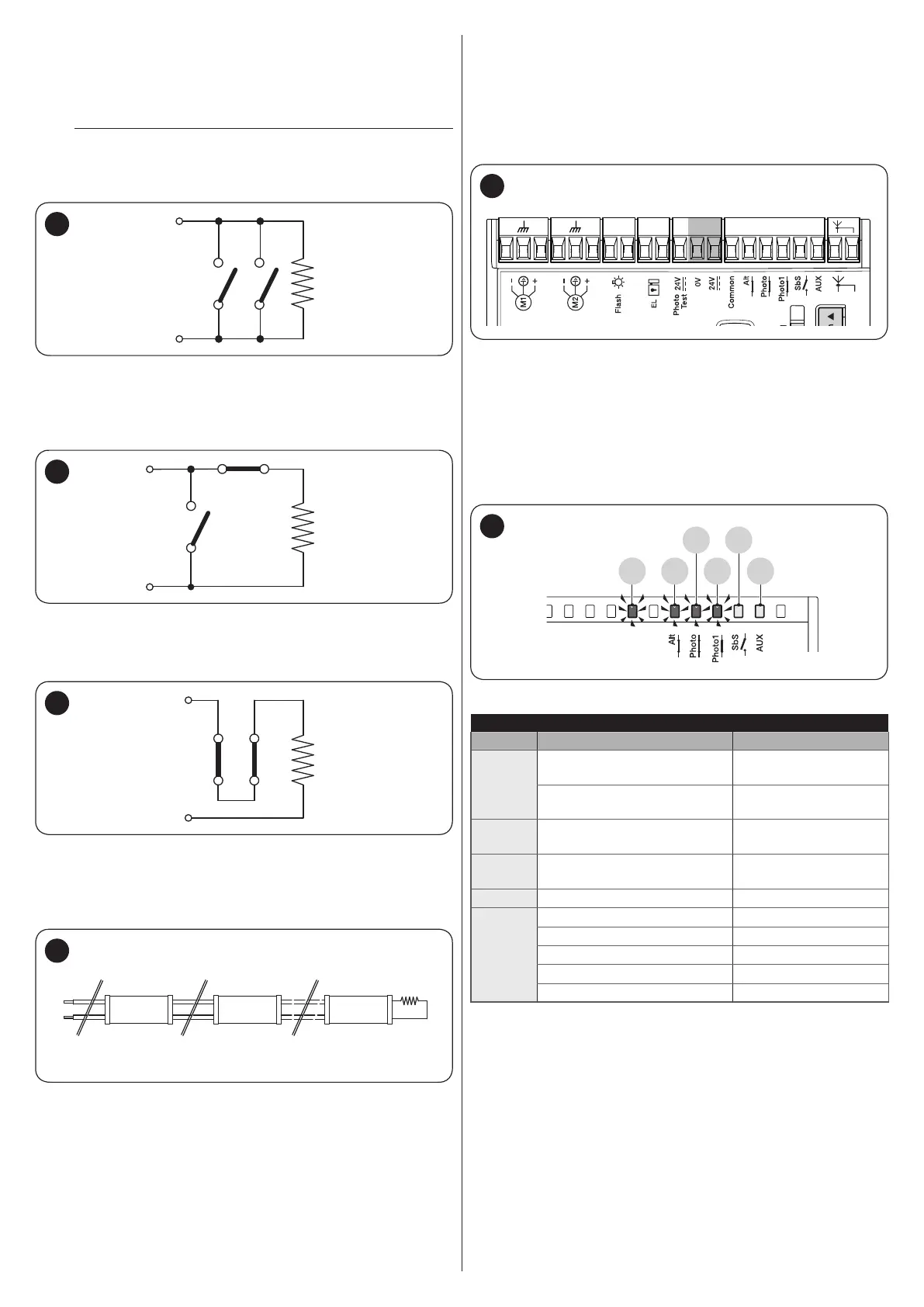
4.3 INITIAL START-UP AND ELECTRICAL
CONNECTIONS TEST
After powering the control unit, carry out the following checks:
1. check that terminals “6-7” have roughly 30 VDC voltage
(“Figure 16”). If the values do not match up, immediately
disconnect the power supply and carefully check the con-
nections and supply voltage.
M M 5 6 7 8 9 10 11 12 131 2 3 4M M
16
2. after the quick initial ash, the “OK” LED will signal the
correct operation of the control unit by ashing regularly
every second. When there is a variation on the control unit
inputs, the “OK” LED will emit a quick double ash to sig-
nal that the input has been recognised
3. if the connections have been made correctly the “NC”-
type inputs must have the corresponding LED lit, while the
“NO”-type inputs must have the corresponding LED off
(refer to “Figure 17“ and to “Table 4”).
L9
OK
L10
L11
L12
L13
17
Table 4
INPUT-LED MATCHES
Input Type of input LED status
ALT
(STOP)
ALT (STOP) NC
L9 lit
(Only after point 5)
8.2 kΩ FIXED RESISTOR
STOP
L9 lit
(Only after point 5)
FOTO
(PHOTO)
NC L10 lit
FOTO1
(PHOTO1)
NC L11 lit
Sbs
NO L12 off
AUX
PARTIAL OPEN type 1 - NO L13 off
PARTIAL OPEN type 2 - NO L13 off
OPEN ONLY - NO L13 off
CLOSE ONLY - NO L13 off
PHOTO2 - NC L13 lit

 Loading...


