6 – ENGLISH
4.2 WIRING DIAGRAM AND DESCRIPTION OF CONNECTIONS
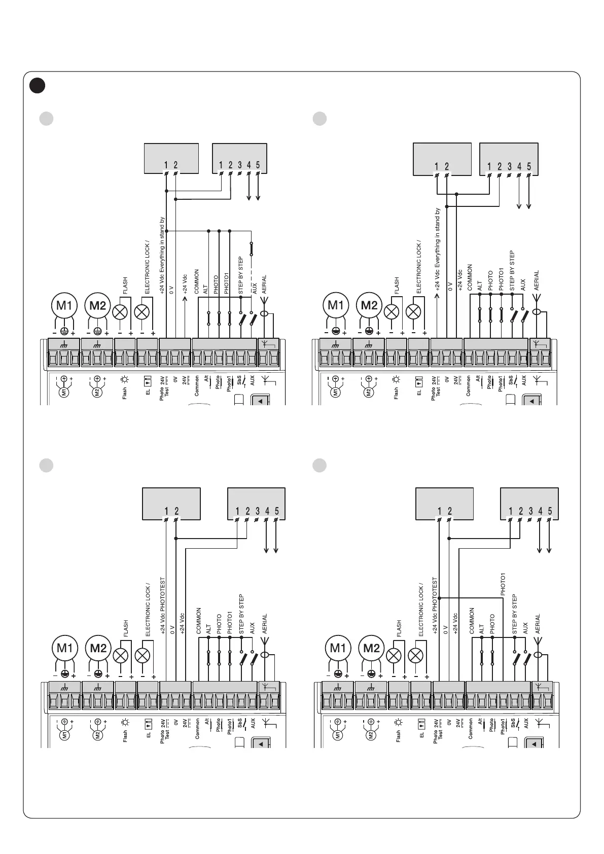
4.2.1 Wiring diagram
M M 5 6 7 8 9 10 11 12 131 2 3 4M M
TX RX
PHOTO2
5 - 10 RX = PHOTO
5 - 11 RX = PHOTO1
5 - 13 RX = PHOTO2
OGI
M M 5 6 7 8 9 10 11 12 131 2 3 4M M
TX RX
8-10 RX = PHOTO
8-11 RX = PHOTO1
8-13 RX = PHOTO2 (AUX)
OGI
TX RX
8-10 RX = PHOTO
8-11 RX = PHOTO1
8-13 RX = PHOTO2 (AUX)
M M 5 6 7 8 9 10 11 12 131 2 3 4M M
OGI
Connection with “Stand-by all” active
(energy saving)
A
Standard connection: without using the
“Stand-by all” and without the “Phototest”
B
Connection without the “Stand-by all”
and with the “Phototest”
C
TX RX
8-10 RX = PHOTO
M M 5 6 7 8 9 10 11 12 131 2 3 4M M
OGI
Connection without the “Stand-by all”, with the
“Phototest” and without the “Photo1”
D
7

 Loading...


