6 Using the contact signal functions
6-2 SC07 Contact signal card specifications
BN50T/BN75T/BN100T/BN150T/BN220T/BN300T
6-4
6-2-4 Contact Signal circuit
Signal output (BL, TR, BU, WB)
UPS Stop Signal input (BS)
Remote ON/OFF
BL
TR
BU
WB
BS
COM
2.4V
560Ω
10V
10KΩ
Remote ON/OFF(+)
Remote ON/OFF(-)
6-2-5 Example of the use of the Contact Signal circuit
Example of BU signal output circuit and
the connected circuit
Example of BS signal input circuit
and the connected circuit
To port
on PC
4.7K
TLP521
Inside of
UPS
External
Circuit
+12V
1KΩ
C2
C1
+5V
C1,C2:0pFtoseveral
thousand pF
(Consider the capacity according to the
operating environment.)
*
COM
UPS side
GND
C2458
BS
From port on PC
12V 1K
1.2K
TLP521
System side
Connecting cable
(twisted or shielded)
Remote ON/OFF circuit
Example of
remote ON/OFF
UPS side
remote ON/OFF(
+
)
remote ON/OFF(
-
)
6 Using the contact signal functions
6-2 SC07 Contact signal card specifications
BN50T/BN75T/BN100T/BN150T/BN220T/BN300T
6
6-5
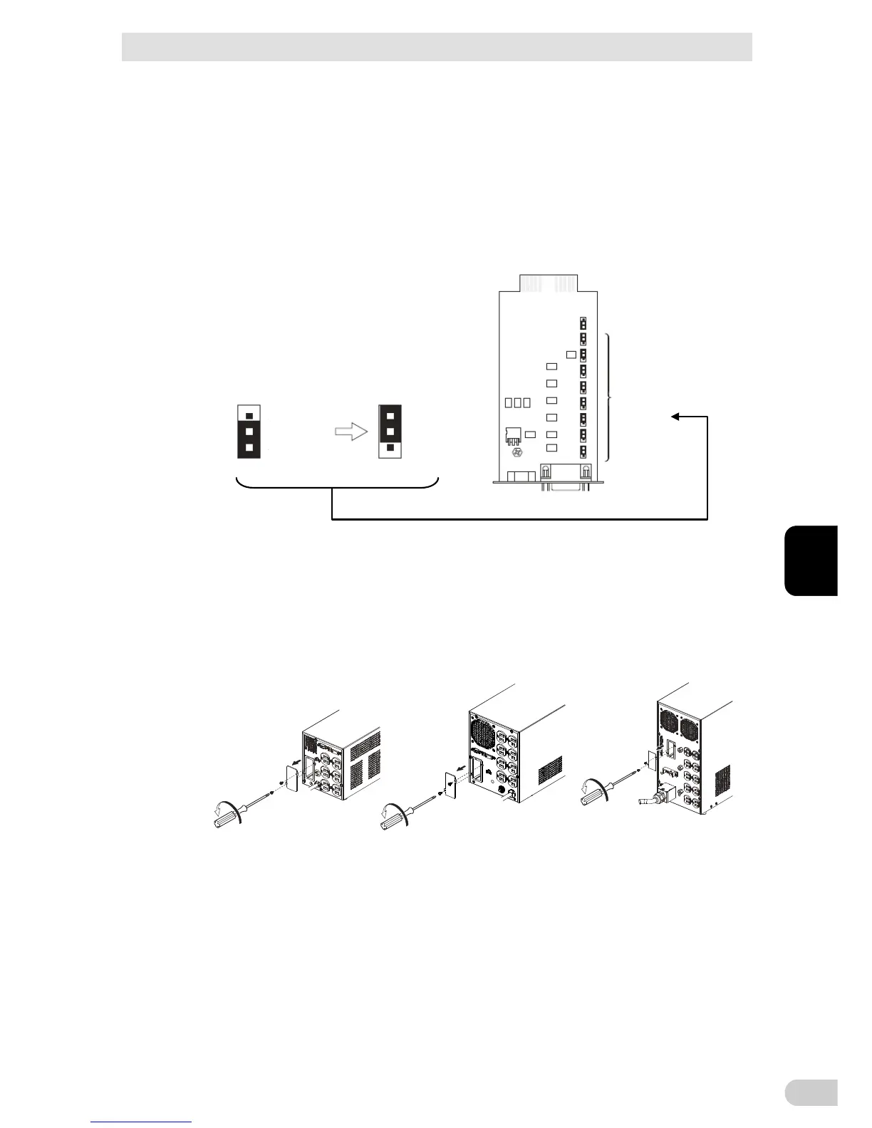
6-2-6 Items that can be set using the contact signal card
Setting up when using the unit in the SC05 compatible mode
Jumper settings
By making jumper settings, the contact signal card SC05/06 connector pin assignments
can be changed.
Turn over the contact signal card, and change the contact signal card’s JP2 to JP9
jumper settings (8 settings) to "SC05/06".
JP10
JP2 to JP9
Jumper settings
(8 digits)
<Before change>
<After change>
SC05/06
SC07
SC05/06
SC07
Note 1: Use the [SC05/06/07] side for JP10
Note 2: Factory settings: SC07 side for JP2 to JP9, SC05/06/07 side for JP10
6-2-7 Insert method of contact signal card
1
. Remove the screws above and below the option slot (2 screws) on the back of the unit,
and remove the cover.
<BN50T/75T> <BN100T/150T> <BN220T/300T>
 Loading...


