5
1-1-5 New/Improved Commands for the CPU Host Interface
New C-mode commands have been added for the CPU Host Interface and the
functionality of existing commands has been improved as follows:
New Commands
• RL/WL: Read and write commands for the CIO Area.
• RH/WH: Read and write commands for the CIO Area.
• CR: Read command for the DM Area.
• R#/R$/R%: SV read commands.
• W#/W$/W%: SV change commands.
• *: Initialization command.
Improved Commands
• The Link Area (CIO 1000 to CIO 1063) and Holding Area (CIO 1200 to
CIO 1299) can now be specified for the KS, KR, KC, and QQ commands.
• CVM1-CPU21-EV2 can now be read for the MM command.
The above new and improved commands can also be used with all V1 CPUs
with lot numbers in which the rightmost digit is 5 (jjj5) or higher.
Note The above new and improved commands cannot be used with the
CV500-LK201 Host Link Unit.
1-2 System Configuration
A Host Link System can be connected using RS-232C and/or RS-422 lines.
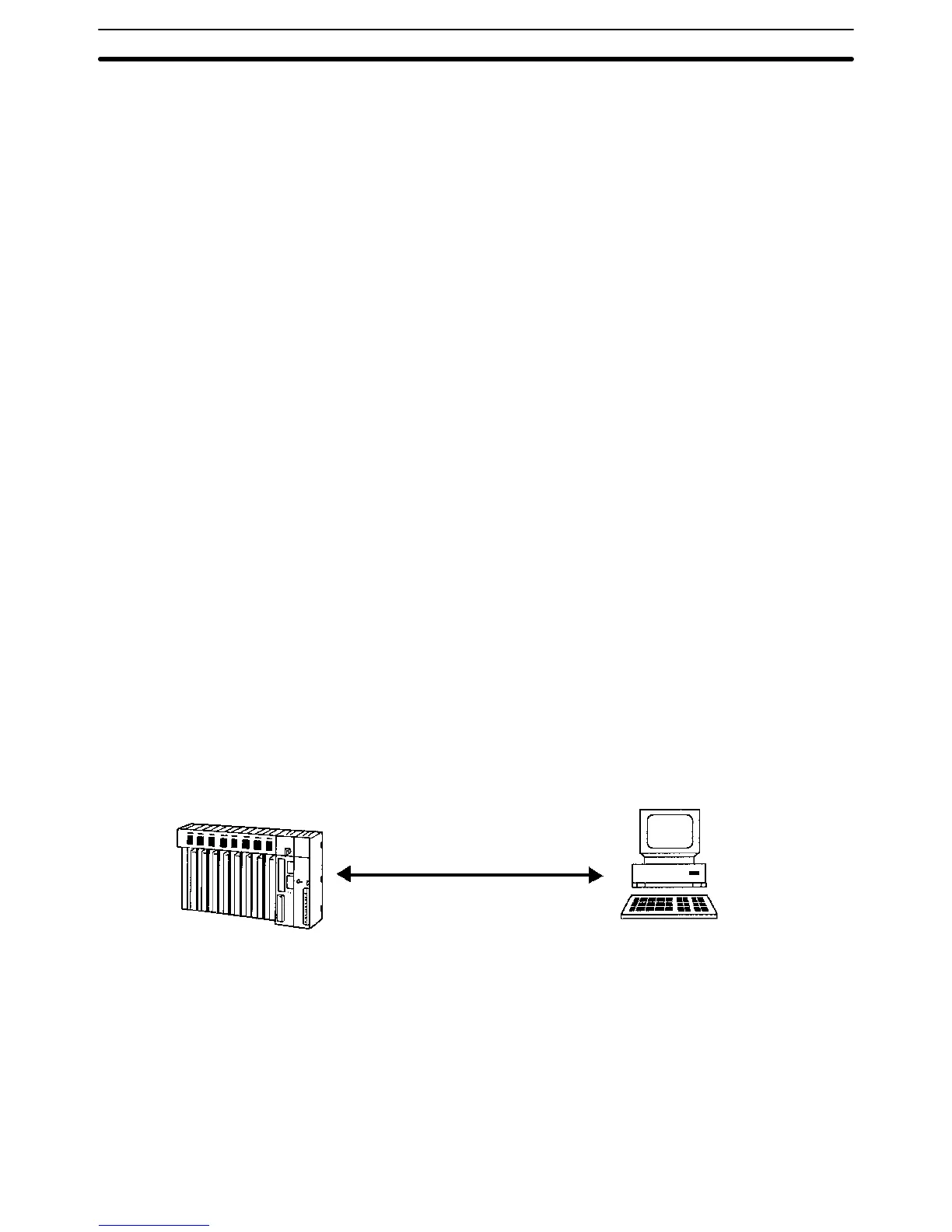
1-2-1 RS-232C
If a RS-232C line is used to connect a Host Link System, only one PC can be
connected to the host computer.
Transmission Distance The maximum transmission distance varies with the method in which a host
computer and PC are connected. There are three connection methods avail-
able: via wire cable, via Optical Fiber Cable and an Optical Interface, and via
optical fiber cable and Link Adapters.
CV-series PC
RS-232C
Host computer (mainframe, personal
computer, or mini-computer)
RS-232C Cable The maximum transmission distance is 15 m if a host computer and PC are con-
nected via RS-232C cable.
Optical Interface The maximum transmission distance is 500 m if a host computer and PC are
connected via two Z3RN-A-5 Optical Interfaces and a Z3F2-4DjM Optical Fi-
ber Cable. The following accessories are necessary. Here, RS-232C cable con-
nects the PC to one Optical Interface and the host computer to the other Optical
Interface, and the Optical Fiber Cable connects the two Optical Fiber Interfaces.
The AC Adapters provide power to the Optical Interfaces.
System Configuration Section 1-2

 Loading...


