40
Note It is not necessary to connect these terminals before connecting the host com-
puter to the Host Link Unit as long as the CTS selector is turned ON.
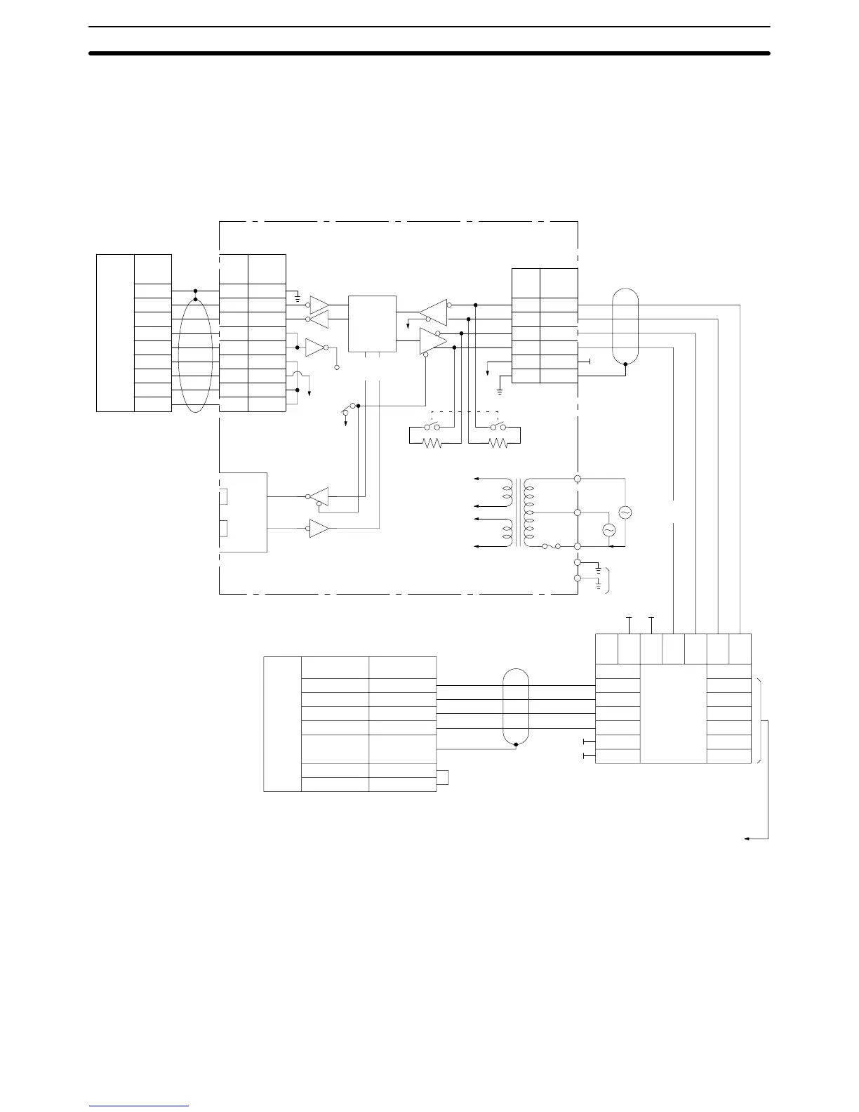
3-8 1-to-N Connection Example
The following diagrams show connections between the Host Link Unit and Link
Adapters and between the Link Adapters and host computer.
FG
SD
RD
RS
CS
DR
SG
CD
ER
1
2
3
4
5
6
7
8
20
1
2
3
4
5
6
7
8
20
SDA
SDB
RDA
RDB
SG
FG
9
5
6
1
3
7
731659
9
5
6
1
3
7
9
5
6
1
3
7
1
2
6
8
4
5
0 V
0 V
0 V
0 V
Pin
no.
RS-
232C
inter-
face
Pin
Host computer RS-232C
OR/se-
lection
circuit
Pin
no.
Sym-
bol
RS-422
Termination resistance
100
VAC
5 V
24 V
Fuse
FG
LG
3G2A9-AL004-(P)E Link Adapter
Trans-
mission
Recep-
tion
Shield
External
connection
Shield
CTS
selection
Pin
no.
Pin no.Pin no.
RS-422
interface
To 100 Ω
max.
AC pow-
er supply
200
VAC
RS-
422
inter-
face
SDA (SD –)
SDB (SD +)
RDA (RD –)
RDB (RD +)
FG
RS
CS
Connector
hood
Signal
Shield
Host Link Unit (or CPU)
Pin
3G2A9-AL001 Link Adapter
To 3G2A9-AL001
Link Adapter, CPU
or Host Link Unit
Sym-
bol
*The RS and CS terminals
need not be connected on the
Host Link Unit as long as the
CTS selector is turned ON
Note 1. To connect more than one PC to a host computer, used the 3G2A9-AL004-E
or 3G2A9-AL004-PE Link Adapter (for RS-232C-to-RS-422 cable conver-
sion) and the 3G2A9-AL001 Link Adapter (to branch to other Units).
2. The shield of the cable must be connected to the connector hood of the PC
for lines connecting PCs to Link Adapters, and to pin 7 on one and only one
Link Adapter on lines connecting two Link Adapters.
3. Leave Host Link Unit pins 3, 4, 5, 7, and 9 unconnected. (Leave CPU pins 3,
7, and 9 unconnected and short-circuit pins 4 and 5.)
1-to-N Connection Example Section 3-8

 Loading...


