37
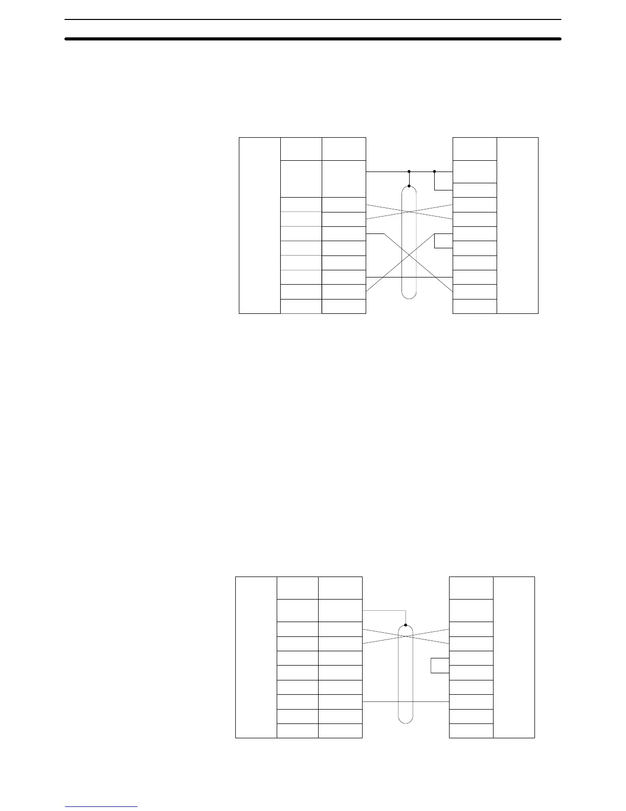
Half Duplex The following diagram shows 1-to-1 host link connections using communica-
tions port 2 in half duplex. Half-duplex communications must be set using the
Host Link Unit’s CPU Bus Unit System Setup.
Signal
name
SD (TXD)
RD (RXD)
RS (RTS)
CS (CTS)
SG (GND)
2
3
4
5
9
FG
CD (DCD) 7
RS-232C
interface
Pin
number
2
3
4
5
6
7
8
20
RS-232C
interface
1
Pin
number
Host Link Unit Host computer
Connector
hood
Shield
Connector
hood
Note 1. Pins 1, 6, and 8 of the Host Link Unit must be connected when RS-422 is
used. These pins must not be connected when using RS-232C.
2. The CTS selector of the Host Link Unit must be turned ON (fixed to 0 V).
3-6-2 Host Link Unit Connection to PT
The diagrams below show 1-to-1 host link connections using OMRON’s NT20M
or NT600M PTs and the Host Link Unit via the PT’s NT600M-LK201 Host Link
Interface Unit. The connection method varies with the port.
The following diagram shows the connections via communications port 1.
Signal
name
RS-232C
interface
RS-232C
interface
Pin
number
Port 1 Host Link Interface Unit
Pin
number
SD (TXD)
RD (RXD)
RS (RTS)
CS (CTS)
SG (GND)
2
3
4
5
7
FG
3
4
5
6
7
8
20
2
Connector
hood
1
Shield
Connections via
Communications Port 1
1-to-1 Connection Examples Section 3-6

 Loading...


