6-8 Special Screens
•
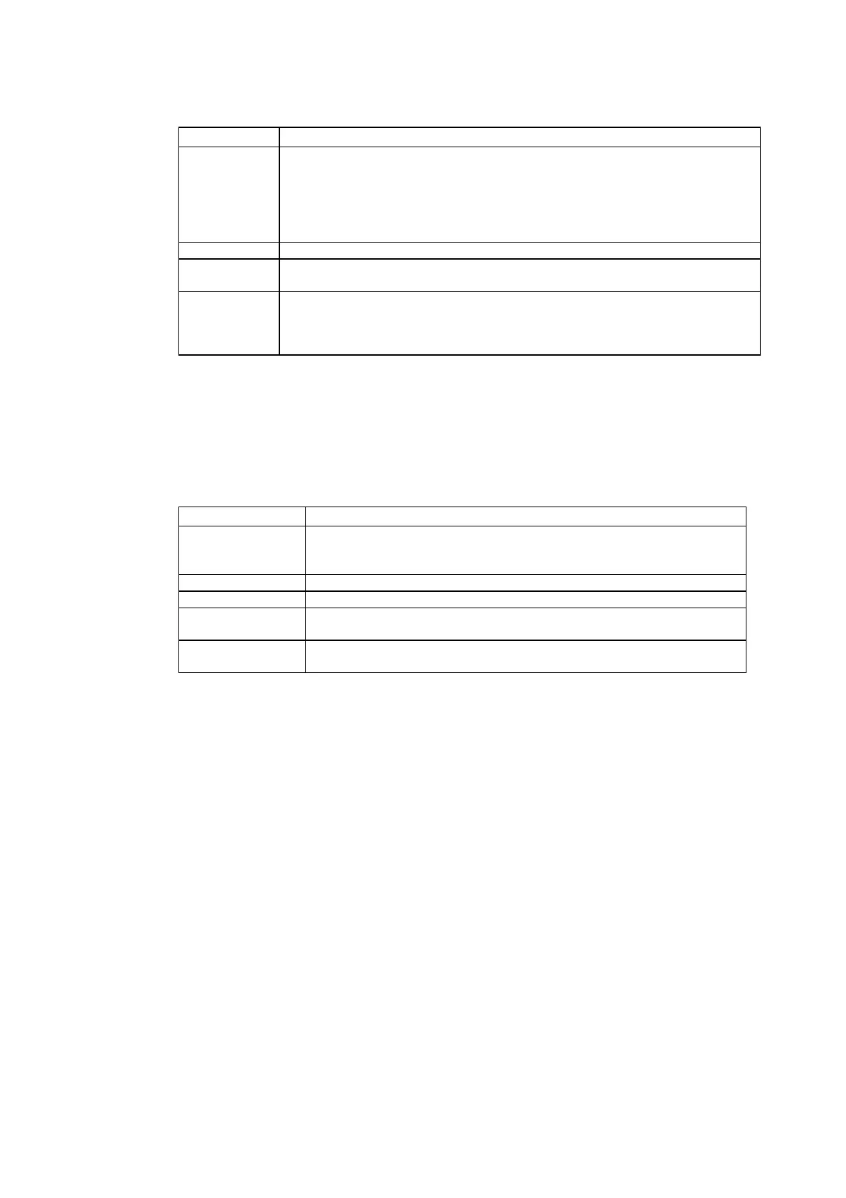
Setting and Display Items in Communication Test Screen
Item Details
Send to Sets the address of the transmission destination in the format (network ad-
dress).(node address).(unit number).
Sets the following addresses when performing a communications test for a node
connected to serial port A or B.
• Serial port A: 111.1.0
• Serial port B: 112.1.0
Send message Sets the FINS command being to be sent.
Number of
sends
Displays the number of times messages are transmitted. The number of times is
fixed to 1.
Receive Time-
out
Sets the time before the message timeout occurs. Displays an error message
when the timeout time is exceeded after transmission.
The setting time is applicable for Ethernet only. For serial communications, the
timeout monitor time set from the Comm Tab is used.
4. Press the Start Button to start transmission.
The sending indicator will remain lit until the transmission is completed.
After transmission, the Receiving indicator will remain lit until reception is completed.
5. If communications are normal, a response will be received from the transmission destination and
the following items will be displayed. Refer to the FINS Command Reference Manual (W227) for
details on FINS commands and information displayed in comments.
• Display Items in Communication Test Screen
Item Details
SID (See note 1.) The SID used for transmission is displayed as a hexadecimal.
The SID is incremented between 0 and 0xFF and returns to 0 after 0xFF is
exceeded.
Received header Displays the FINS header that is received. (See note 2.)
Received message Displays the received message.
ms Displays the time lapsed in ms from sending the FINS command until re-
ceiving the FINS response.
Comment Displays the status, such as "normal completion," according to the comple-
tion code after reception.
Note 1. SID is the source process ID.
2. The FINS header is the header that precedes the FINS command.
Refer to the FINS Command Reference Manual (W227) for details on FINS commands.
6. Press the Back Button to return to the Special Screen.
6-8-6 Video Configuration
A Video Input Unit can be mounted to the PT to display images by connecting video devices.
The user can adjust the image and output signals to a Vision Sensor from this window.
This section describes only the procedure for opening the window. For details, refer to 2-18-
10 Video Configuration in the NS Series Programming Manual.
The Video Configuration Window can be access by selecting the System Menu and clicking
the Special Screen Tab as shown below.
6-49
 Loading...


