3-8 Installing the Controller Link Interface Unit
3-8-4 Wiring
This section describes the method for wiring the network communications cable to the Con-
troller Link Support Board.
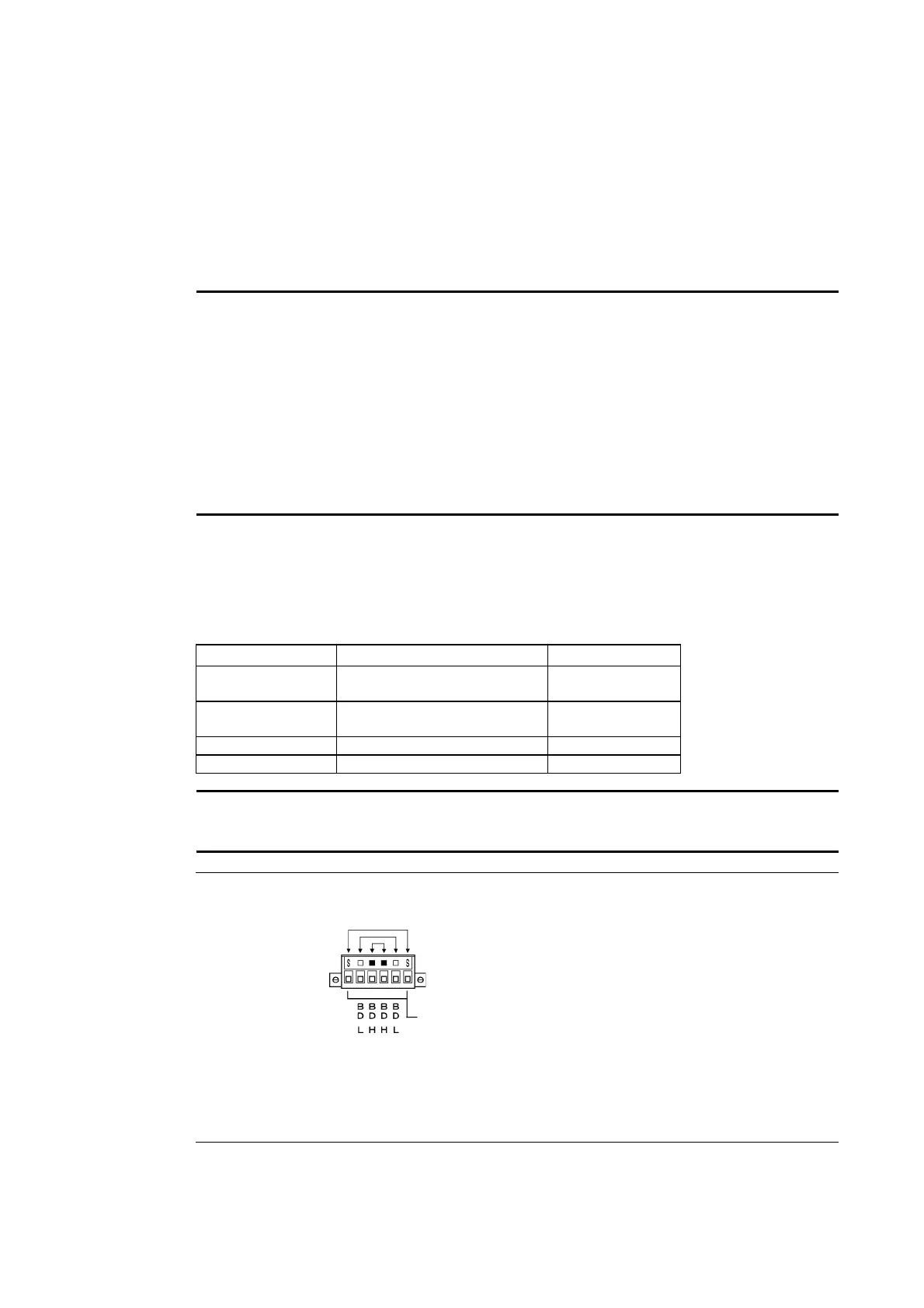
● Wiring the Communications Cable
Wire the communications cable to connect identical signals.
Note • Use the cable specified for the communications cable.
• Keep communications cables separated from power lines or high-tension lines to prevent
influences from electronic noise.
• Ground the shield of the communications cable at one end of the network. Do not ground
the shield at both ends.
• Do not connect the shield cable of the communications cable to a ground that is also being
used for power-system devices, such as inverters.
• Do not run wiring outdoors. If outdoor wiring is necessary, take protective measures against
lightening, such as underground wiring or wiring inside pipes.
• Always turn OFF the power to PT before connecting the communications cable or install-
ing/removing the connector.
• Use the connector attached to the Controller Link Support Board.
Connecting the Communications Cable
Connect the communications cable to the Controller Link Support Board after first connecting
it to the cable connector provided.
Use one of the twisted-pair cables listed below as the communications cable.
Model Manufacturer Remarks
Li2Y-FCY2x0.56qmm KROMBERG & SHUBERT, D
partment KOMTEC
e- German company
1x2xAWG-20PE+Tr.
CUSN+PVC
DRAKA CABLES INDUSTRIAL Spanish company
#9207 BELDEN American company
ESVC0.5x2C Bando Densen Co. Japanese company
Note • Use the cables listed above.
• Normal communications may not be possible if a communications cable other than those
listed above is used.
Reference • Terminals for the same signal on the Controller Link Support Board’s connector are
connected internally.
• The thickness of the ground wire connected to the Controller Link Support Board’s
connector must be less than 2.5 mm
2
.
• Connect to the network using the special connector provided with the Controller Link
Interface Unit.
3-50
 Loading...


