4 Designing the Power Supply System
4 - 2
NX-series NX1P2 CPU Unit Hardware User’s Manual (W578)
4-1 Power Supply System and Design
Concepts
This section describes the power supply system for the CPU Rack of an NX-series NX1P2 CPU Unit
and the design concepts.
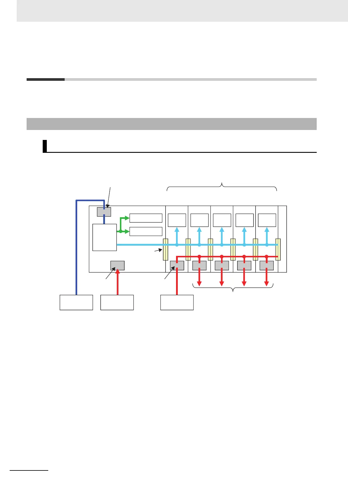
An example of a power supply system configuration diagram for the CPU Rack of an NX1P2 CPU Unit
is shown below.
4-1-1 Power Supply System and Types of Power Supplies
Power Supply System Configuration Diagram
Internal
circuits
NX Units (8 max.)
Unit power supply terminals
I/O
To external devices
End Cover
I/O power supply
terminals
Cn(+V)/0Vn
terminal
Built-in I/O
NX bus connector
NX Unit power supply
Internal
circuits
Internal
circuits
Internal
circuits
Internal
circuits
Unit power supply
(24 VDC)
NX-series
NX1P2 CPU
Unit
Additional I/O Power
Supply Unit
I/O power supply
(24 VDC, etc.)
I/O power supply
(24 VDC)
Internal
power
supply
circuit
Internal circuits
Option Board
○

 Loading...


