5 - 25
5 Installation and Wiring
NX-series NX1P2 CPU Unit Hardware User’s Manual (W578)
5-3 Mounting Units
5
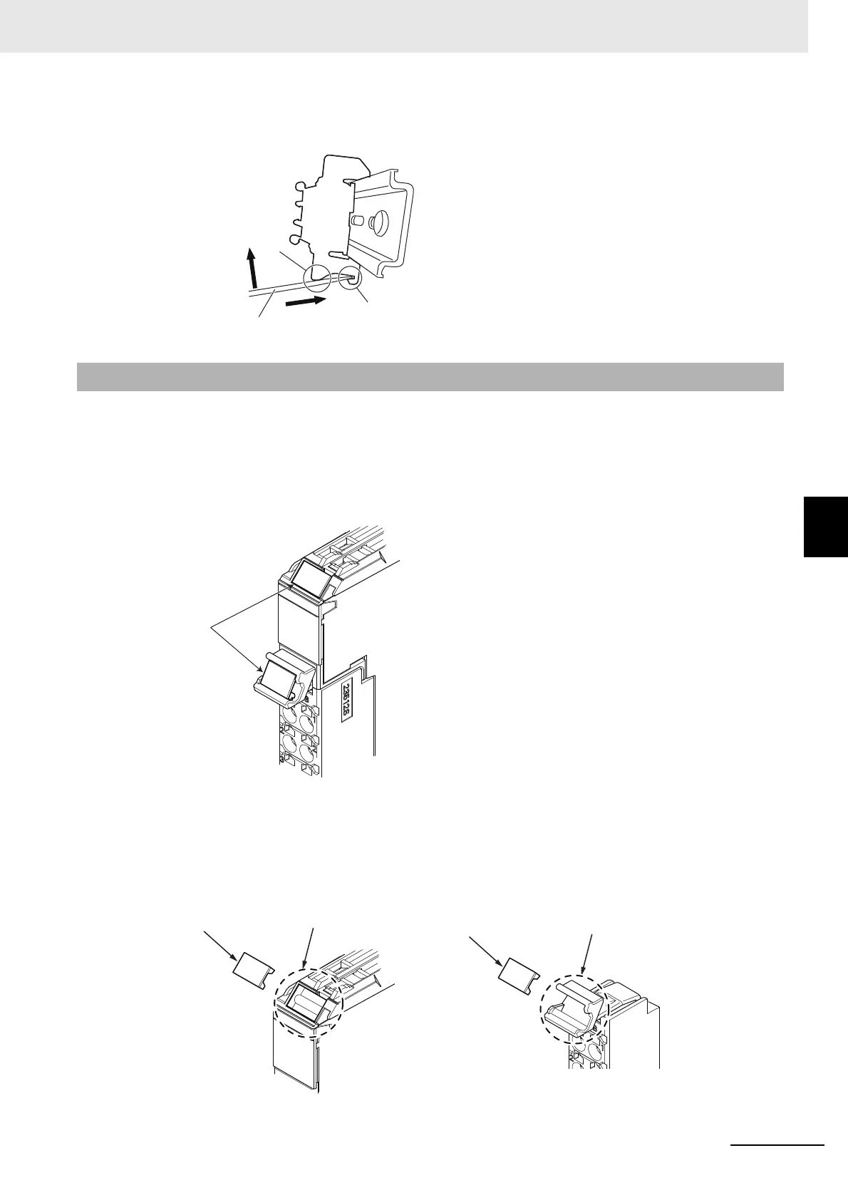
5-3-7 Attaching Markers
To remove an End Plate 1) insert the tip of a flat-blade screwdriver into groove “a” and 2) use “b” as
a fulcrum and lift the end of the screwdriver, as shown in the following diagram.
Markers can be attached to NX Units and their terminal blocks to identify them.
The plastic markers made by OMRON are installed for the factory setting. The ID information can be
written on them.
Commercially available markers can also be installed.
Replace the markers made by OMRON if you use commercially available markers now.
The marker attachment locations on the NX Units depend on the type of external connection terminals.
Refer to the user’s manual for the NX Units that you will use for the marker attachment locations.
Installation Method
Insert the protrusions on the markers into the marker attachment locations on the NX Units and ter-
minal blocks on NX Units.
5-3-7 Attaching Markers
a
b
Flat-blade screwdriver
1)
2)
Marker
Marker
Marker attachment location
Marker attachment location
<Terminal Block><Units>

 Loading...


