3 - 27
3 Configuration Units
NX-series NX1P2 CPU Unit Hardware User’s Manual (W578)
3-4 Analog I/O Option Board
3
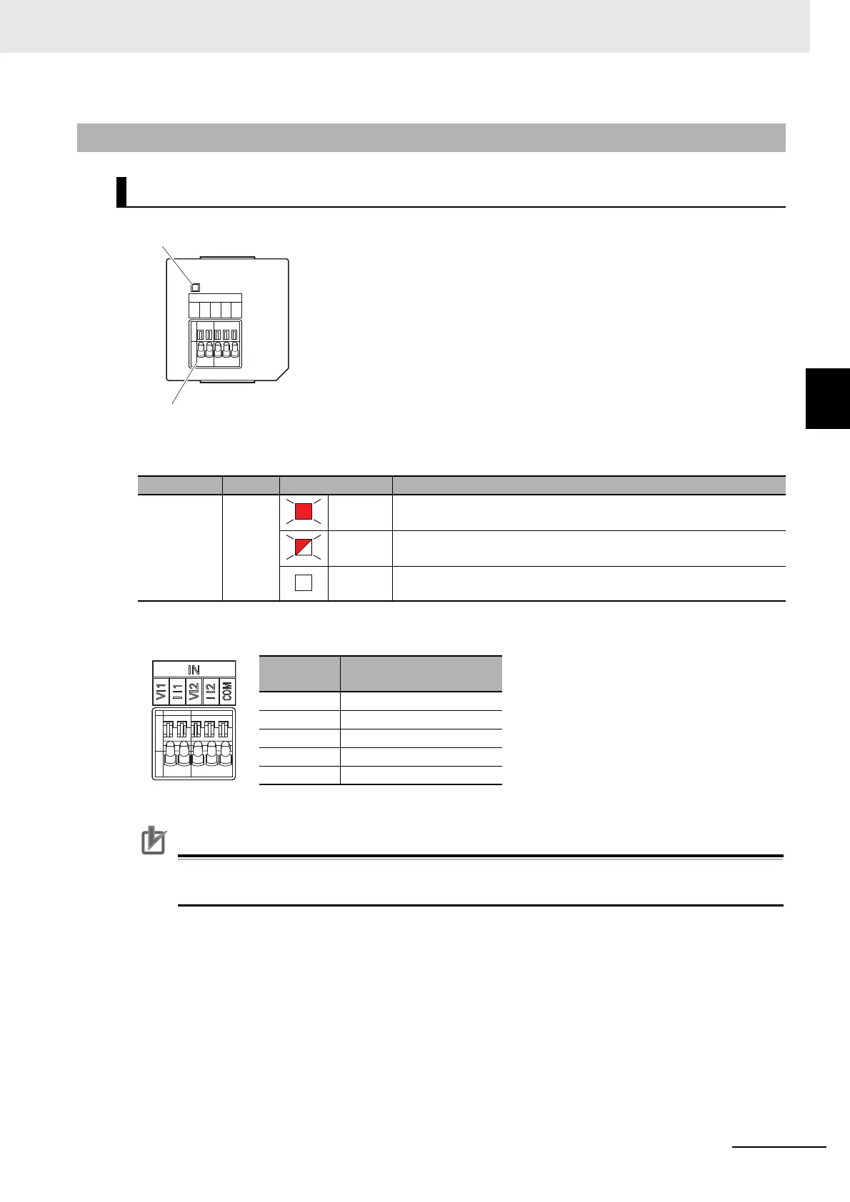
3-4-3 Part Names and Functions
Status Indicator
Analog Input Terminal Array
Precautions for Correct Use
When you use the current input, be sure to short-circuit V I1 with I I1, and short-circuit V I2 with
I I2.
3-4-3 Part Names and Functions
Analog Input Option Board (NX1W-ADB21)
Indicator Color Status Description
ERR Red Lit. An Option Board Error (WDT) was detected by the self-diagnostic
function.
Flashing. A Communications Error occurred between the Option Board and
the CPU Unit.
Not lit. Normal operation
Abbrevia-
tion
Signal name
V I1 Voltage input 1
I I1 Current input 1
V I2 Voltage input 2
I I2 Current input 2
COM Input common
ERR
IN
VI1
I I1
VI2
I I2
COM
Analog input terminal block
Status indicator

 Loading...


