4 Designing the Power Supply System
4 - 16
NX-series NX1P2 CPU Unit Hardware User’s Manual (W578)
Procedure
1 Use the following formula to calculate the total current consumption from the I/O power supply.
2 Find the I/O power supply voltage and make sure that it is within the voltage specifications of the
I/O circuits of the NX Units and the connected external devices.
If the I/O power supply voltages of the connected external devices are different, connect an Additional
I/O Power Supply Unit at the point where the I/O power supply voltage changes and then perform simi-
lar calculations to design a system that meets the power supply conditions. The same method is used
to separate the power supply systems. Connect an Additional I/O Power Supply Unit at the point where
the power supply systems are to be separated and then perform similar calculations to design the over-
all system to meet the power supply conditions.
Unlike supplying power from the NX bus, there is no specific design method for supplying I/O power
from external sources.
Calculate the total current consumption from the I/O power supply for the NX Units to be supplied
power from an external source.
Refer to the user’s manuals of the NX Units for the total current consumption from the I/O power supply.
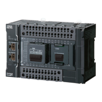
The I/O power supply for built-in I/O is separated from NX bus, so there is no specific design method.
Calculate the total power consumption from the I/O power supply provided from an external source.
For the PNP (sourcing) type built-in output, an external source is required to supply power between the
common terminal and 0 V terminal in order to drive the internal circuits. When you calculate, include
this power supply used to drive, too.
Refer to Input Specifications on page 3-12 and Output Specifications on page 3-15 under 3-1-4
Terminal Blocks on page 3-10 for the I/O specifications of the built-in I/O.
Total current consumption from the I/O power supply
=(1) + (2) + (3) + (4) + (5)
= 0.0 A + 0.5 A + 0.5 A + 0.0 A + 2.0 A
= 3 A
I/O power supply voltage at (5) = I/O power supply voltage on I/O power supply terminals (Voltage drop per Unit ×
Number of Units passed through)
= 24.00 V 0.06 V × (5 1 Units)
= 23.76 V
Design to Separate the I/O Power Supply
4-3-3 Designing the I/O Power Supply from External Sources
4-3-4 Designing I/O Power Supply for the Built-in I/O

 Loading...