5 Installation and Wiring
5 - 58
NX-series NX1P2 CPU Unit Hardware User’s Manual (W578)
This section gives some wiring examples for the built-in I/O Units and precautions for wiring.
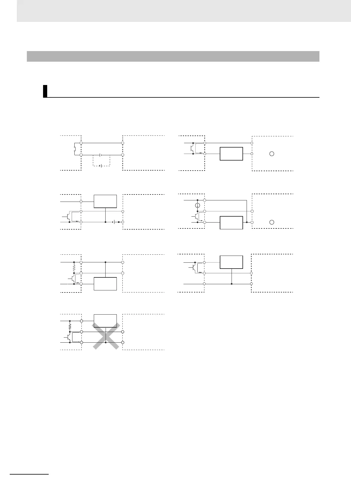
Use the following information for reference when selecting or connecting input devices.
DC Input Devices Which Can Be Connected (DC Output)
5-4-9 Wiring the Built-in I/O
Wiring the Built-in Input
0 V
+
0 V
+
+
IN
0 V
+
COM
IN
IN
0 V
+
COM
COM
0 V
+
+
ININ
COM COM
+
IN
COM
+
IN
COM
Input terminal
block
Input terminal
block
Input terminal
block
Input terminal
block
Input terminal
block
Input terminal
block
Input terminal
block
Sensor
Power
supply
Output
• The circuit below should not be used for I/O devices having a voltage output.
Voltage output
Sensor
Power
supply
Output
Sensor
Power
supply
Output
Output
NPN open-collector output
Contact output
Sensor
Power
supply
Two-wire DC output
NPN current output
Current
regulator
Sensor
Power
supply
PNP current output
Output
Sensor
Power
supply

 Loading...


