3 Configuration Units
3 - 4
NX-series NX1P2 CPU Unit Hardware User’s Manual (W578)
The following two models have the different numbers of the option board slots and built-in I/O points,
but the names and functions of their parts are the same. Refer to 3-1-1 Models and Specifications on
page 3-2 for the CPU Unit models and specifications such as the number of built-in I/O points.
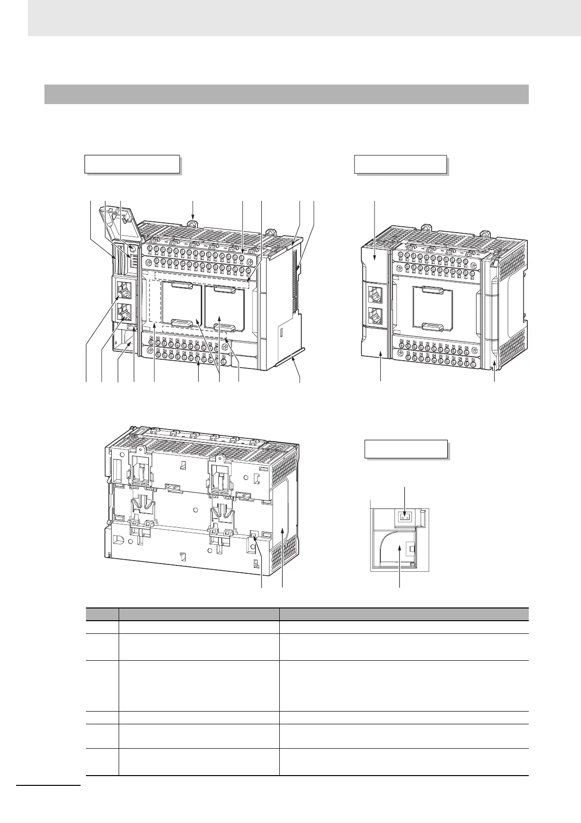
3-1-2 Part Names and Functions
Letter Name Function
A SD Memory Card connector Connects the SD Memory Card to the CPU Unit.
B DIP switch
Used in Safe Mode
*1
or when backing up data
*2
. Normally,
turn OFF all of the pins.
C SD Memory Card power supply switch Turns OFF the power supply so that you can remove the SD
Memory Card.
5-3-8 Installing and Removing the SD Memory Card on page
5-26
D DIN Track mounting hook These hooks are used to mount the Unit to a DIN Track.
E Input terminal block This terminal block is used for wiring for the Unit power supply,
grounding, and built-in input.
F Input indicator Shows the operation status of the built-in input.
Built-in I/O Operation Status Indicators on page 3-9
(A) (B) (C) (D) (G)
(G)(J)
(U)
(H)
(I)
(E)
(F) (Q)
(K) (R)(S)
(T) (N)
(M)
(L)(M)(N)(O)(P)
NX1P2-140 NX1P2-9024
(M) and (N) details

 Loading...


