3 Configuration Units
3 - 26
NX-series NX1P2 CPU Unit Hardware User’s Manual (W578)
The Analog I/O Option Board allows inputs from devices such a variable resistor controls and pro-
cess-control sensors. It also enables you to control inverters.
Analog inputs that can be processed are 0 to 10 V inputs from devices including a variable resistor, and
4 to 20 mA inputs from process-control sensors.
Analog outputs range from 0 to 10 V, which allow the CPU Unit to control inverters directly.
Refer to the NX-series NX1P2 CPU Unit Built-in I/O and Option Board User’s Manual (Cat. No. W579)
for details on how to use the Option Boards.
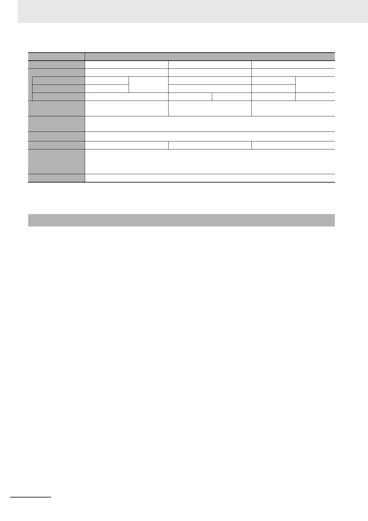
Item Specification
Model NX1W-ADB21 NX1W-DAB21V NX1W-MAB221
I/O Analog input Analog output Analog I/O
Voltage input 0 to 10 V 2 words total --- 0 to 10 V 2 words total
Current input 0 to 20 mA --- 0 to 20 mA
Voltage output --- 0 to 10 V 2 words 0 to 10 V 2 words
Connection type
Screwless clamping terminal
block (5 terminals)
Screwless clamping terminal
block (3 terminals)
Screwless clamping terminal
block (8 terminals)
Applicable wire
size
AWG24 to 20
Dimensions (mm)
*1
*1. Projecting parts such as a terminal block is not included. When the Option Board is mounted to the CPU Unit, it protrudes
through the CPU Unit surface. The details are explained in 5-3-13 Assembled Appearance and Dimensions on page 5-35.
35.9 × 35.9 × 28.2 (W×H×D)
Weight 24 g 24 g 26 g
Power consump-
tion
Included in the CPU Unit power consumption.
The Option Board power consumption is included in the definition of the CPU Unit power consump-
tion.
Isolation method No isolation
3-4-2 Purpose

 Loading...


