5 Installation and Wiring
5 - 20
NX-series NX1P2 CPU Unit Hardware User’s Manual (W578)
This section describes how to mount NX Units to the CPU Unit and how to connect NX Units to each
other.
Markers can be attached to NX Units and their terminal blocks to identify them. To make NX Units
identifiable, attach markers before you install the NX Units. Refer to 5-3-7 Attaching Markers on page
5-25 for details on how to attach markers.
• Always turn OFF the power supply before mounting the NX Units. If the power supply is not
OFF, the Unit may malfunction or may be damaged.
• Do not apply labels or tape to the Units. When the Units are installed or removed, adhesive or
scraps may adhere to the pins in the NX bus connector, which may result in malfunctions.
• Do not touch the pins in the NX bus connector on the Unit. Dirt may adhere to the pins in the
NX bus connector, which may result in malfunctions.
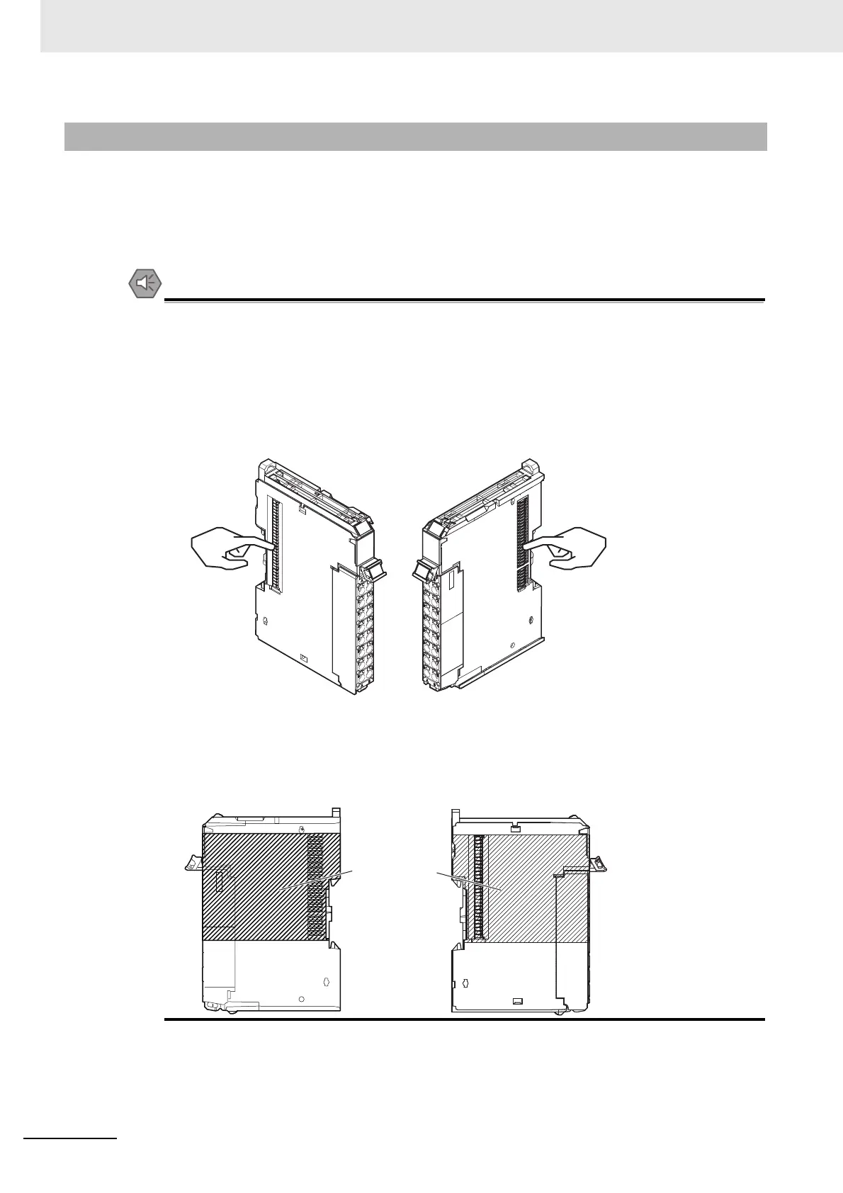
• Do not write on an NX Unit with ink within the restricted region that is shown in the following
figure. Also do not get this area dirty. When the Unit is installed or removed, ink or dirt may
adhere to the pins in the NX bus connector, which may result in malfunctions in the CPU
Rack.
5-3-4 Installing and Connecting NX Units
Example: NX Unit (12 mm width)
NG
NG
Restricted region
(shaded portion)

 Loading...


