3-72
3-4 Cable and Connector Specifications
OMNUC G5-series AC Servomotors and Servo Drives User’s Manual (with Built-in EtherCAT Communications)
3
Specifications
Wiring
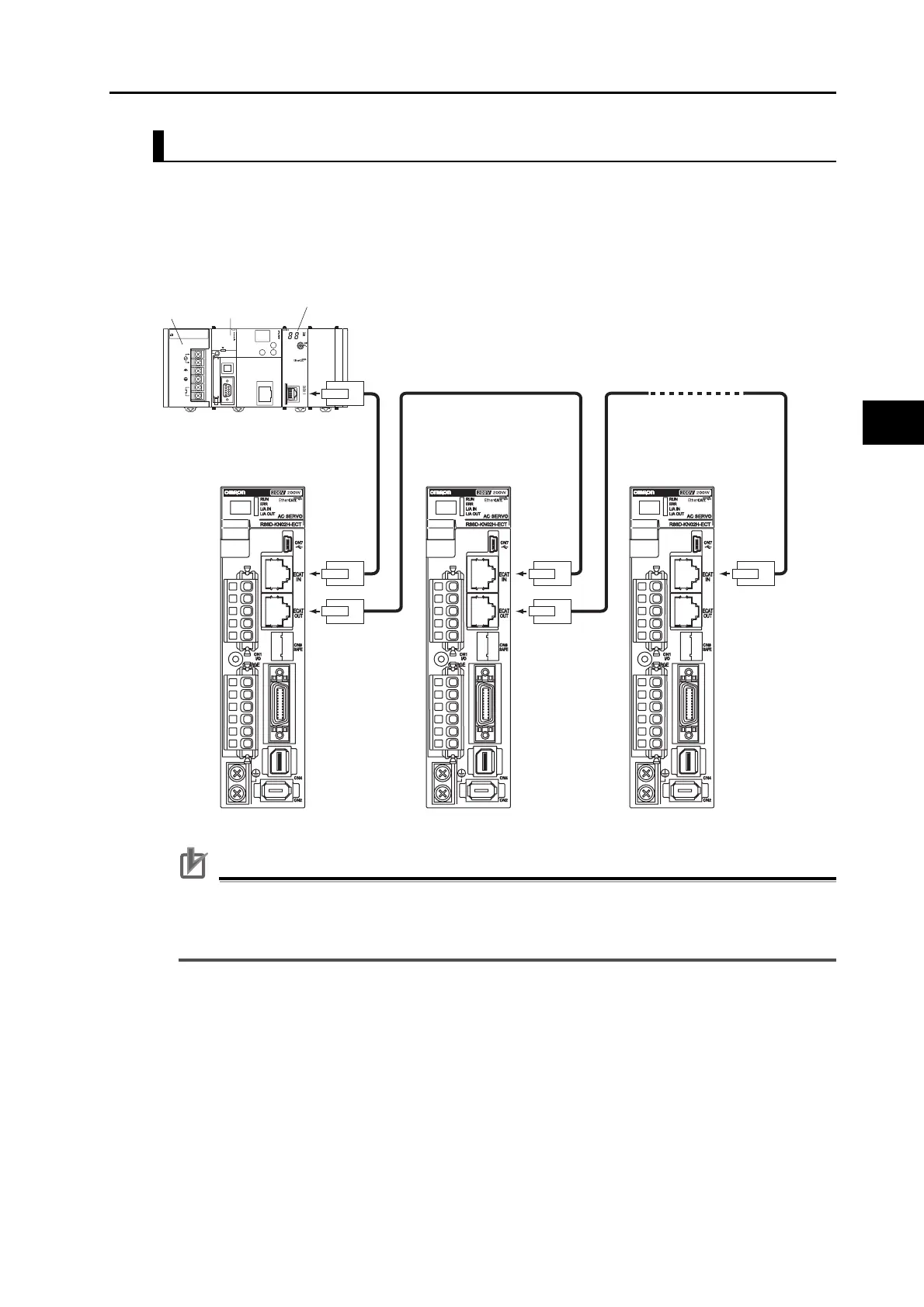
This example shows how to connect a CJ1W-NC281/NC481/NC881/NCF81/NC482/NC882
Position Control Unit to Servo Drives using EtherCAT Communications Cables.
Connect the EtherCAT master to the ECAT IN connector on the first Servo Drive. Connect the
ECAT OUT connector on the first Servo Drive to the ECAT IN connector on the next Servo
Drive. Do not connect the ECAT OUT connector on the last Servo Drive.
Precautions for Correct Use
Always turn OFF the power supply to the Position Control Unit and Servo Drives before
connecting or disconnecting the EtherCAT Communications Cables.
The cable between the two nodes (L1, L2 ... Ln) must be 100 m or less.
L1 L2 Ln
CJ-series
CPU Unit
Power
Supply Unit
Position
Control Unit

 Loading...


