10-4
10-2 Preparing for Operation
OMNUC G5-series AC Servomotors and Servo Drives User’s Manual (with Built-in EtherCAT Communications)
10
Operation
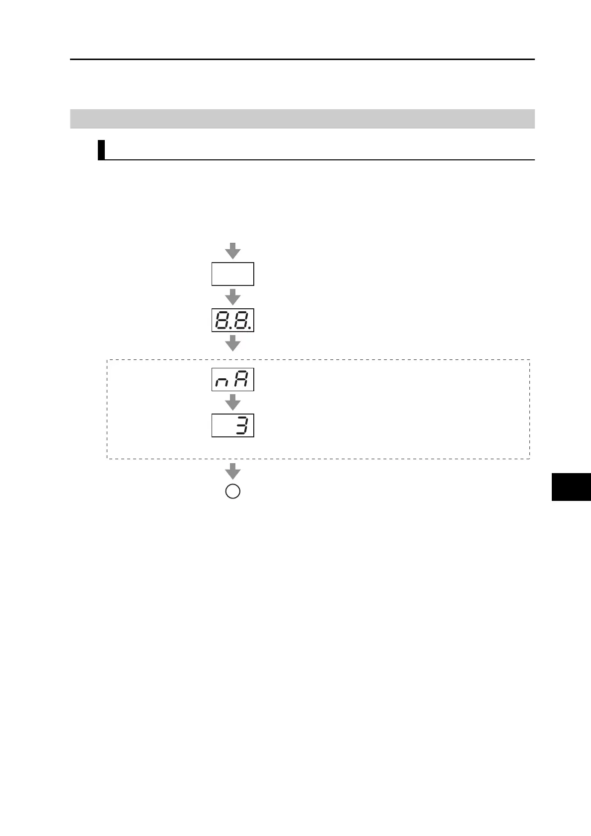
Checking the Displays
7-Segment Display
The 7-segment display is on the front panel. When the power is turned ON, it shows the node
address that is set by the rotary switches. Then the display changes according to the setting
of the LED Display Selection (3700 hex).
An error code is displayed if an error occurs. A warning code is displayed if a warning occurs.
Control power ON
Fully OFF
Fully ON
"nA" (node address, approx. 0.6 s)
Rotary switch setting
(upper digit (×10) = 0, lower digit (×1) = 3)
(It lasts for the period set in the Power ON Address
Display Duration Setting (3701 hex).)
Node Address Display
A
To on the next page

 Loading...


