5-1
5-1 Display Area and Settings
OMNUC G5-series AC Servomotors and Servo Drives User’s Manual (with Built-in EtherCAT Communications)
5
EtherCAT Communications
5-1 Display Area and Settings
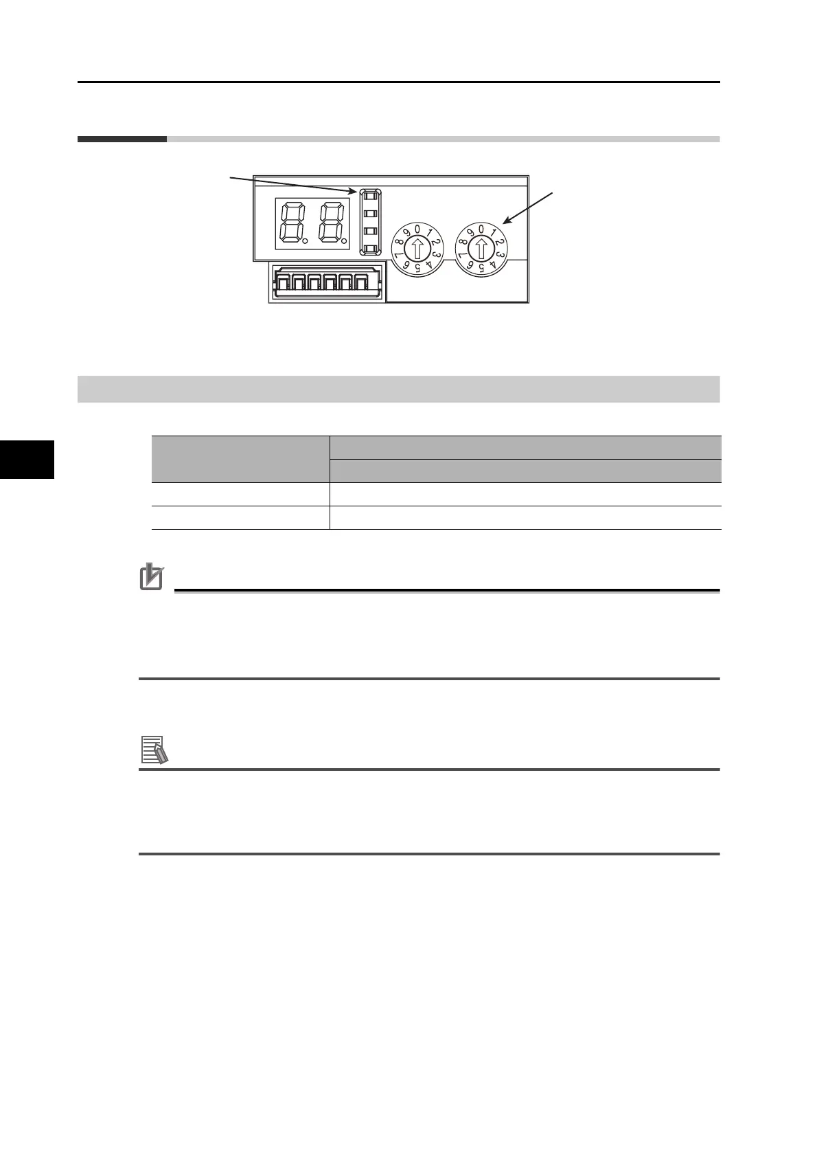
Node Address Setting
The rotary switches in the display area are used to set the EtherCAT node address.
Precautions for Correct Use
Do not change the rotary switch setting after the turning ON the power supply.
The node address rotary switches can be set to between 00 and 99.
The node address used over the network is determined by the value set on the rotary switches.
If the node address is not between 00 and 99, a Node Address Setting Error (Error 88.0) will occur.
Reference
EtherCAT Slave Information File
Information on EtherCAT slave settings is stored in the ESI (EtherCAT Slave Information) file.
Information in this file is used by the master to configure the network and set communications
parameters. This information is in an XML file.
CN5
ADR
x10
x1
Rotary switches for
node address setting
Status indicators
@ RUN
@ ERR
@ L/A IN
@ L/A OUT
Rotary switch setting
Description
Connection to CJ1W-NC281/NC481/NC881/NCF81/NC482/NC882
00 The Position Control Unit sets the node address.
01 to 99 The rotary switch setting is used as the node address.

 Loading...


